Inrush Current Limiter

a technology of inrush current and limiter, which is applied in the direction of circuit arrangement, emergency protective arrangement for limiting excess voltage/current, electrical apparatus, etc., can solve the problems of inrush current tripping of protection device supporting electronic device, inconvenient tripping of mains supply, permanent damage to electronic components of electronic device, etc., to reduce the period in which the system is vulnerable to inrush current and simplify circuit construction.

Active Publication Date: 2017-05-18
KEYMED MEDICAL & INDAL EQUIP
View PDF3 Cites 11 Cited by
  • Summary
  • Abstract
  • Description
  • Claims
  • Application Information

AI Technical Summary

Benefits of technology

[0011]The present invention addresses the problem of how to provide inrush current protection following reconnection of a power supply during a period after the supply has been disconnected, but before the inrush current protection circuit has reset. Without the inrush timer being reset by a separate reset circuit, the time taken for inrush current protection to be reinstated is the time it takes for the decay of charge retained in the electronic components of the inrush timer, such as i...

Problems solved by technology

Such a device may be useful in electronic medical equipment where spontaneous tripping of the mains supply that results from an inrush current is particularly undesirable.
Such a surge of current is known as an inrush current, and may lead to a tripping of a protection device supporting the electronic device or permanent damage to electronic components of the electronic device.
When the device is first switched on, the NTC thermistors are ‘cold’ and thus impede the inrush current and limit the effect of said inrush current on the electronic device.
This resistance will significantly reduce as the NTC thermistors are heated by the current flowing through them, thus providing limited resistance to the final, steady-state current flowing to the device.
A disadvantage of employing NTC thermistors as a means for inrush current protection is that, after the current flowing through them is removed, the NTC thermistors remain ‘warm’ with a low resistance.
Thus if the current is turned off and then on again before the NTC thermistors have been able to cool to a high resistance state, there will be limited or no protection provided to protect against any inrush current associated with this turn on.
Sometimes the current surge will be modest or absent, in which case the equipment will continue as if nothing has happened, but on occasion the surge will be very large and may cause a protection device to trip.
The NTC thermistor...

Method used


Image

  • Inrush Current Limiter
  • Inrush Current Limiter
  • Inrush Current Limiter

Examples


Embodiment Construction

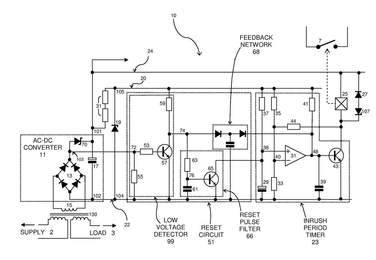
[0042]Preferred embodiments of the present invention are now provided with reference to the accompanying figures.

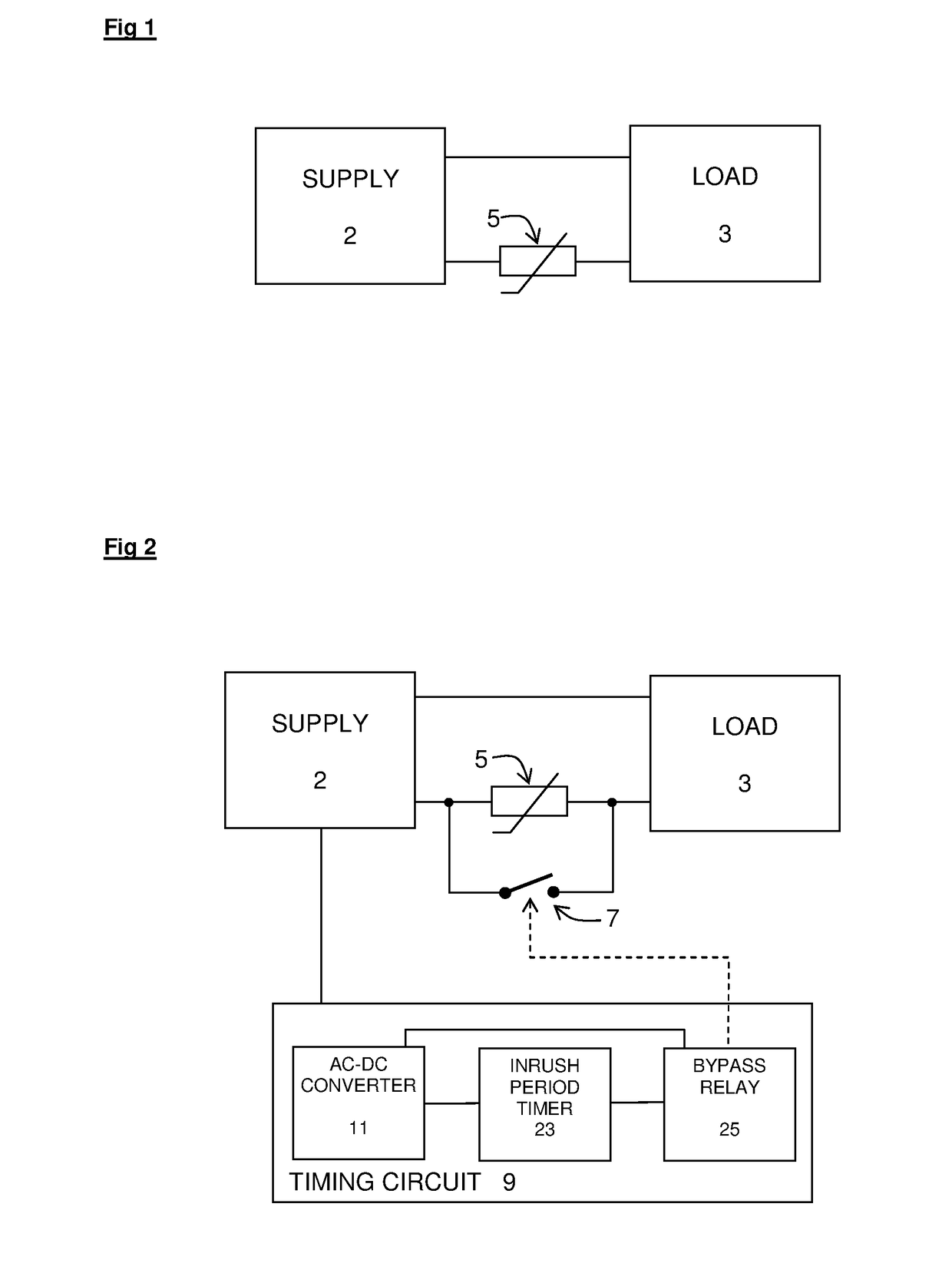
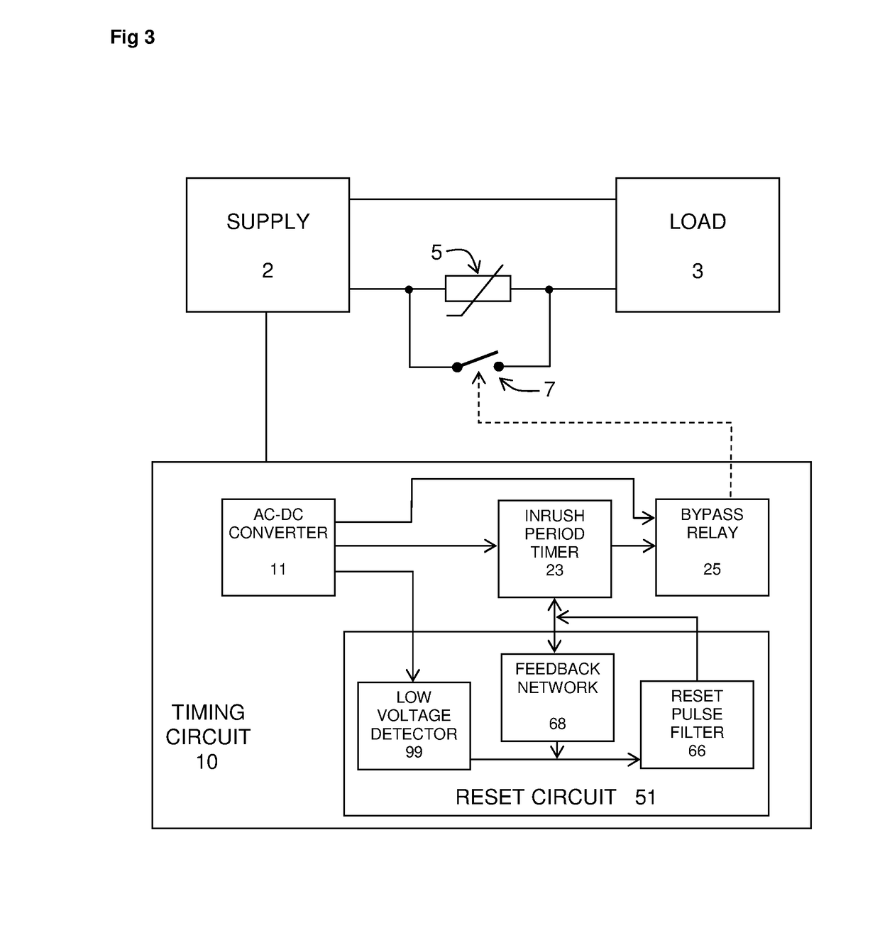
[0043]FIG. 1 shows a basic circuit to provide inrush current protection, well understood by those skilled in the art. A supply 2 is connected to a load 3. Arranged between the supply 2 and the load 3 is an impedance 5, where the impedance 5 may be a resistor, but is preferably a Negative Temperature Coefficient (NTC) thermistor. Hereafter reference will be made to an NTC thermistor, but it is to be understood that alternative impedances may be used. The arrangement of the NTC thermistor 5 between the supply 2 and the load 3 provides a high resistance to currents in a period immediately following an initial turn on of the supply, and low resistance during steady-state operation. Following turn off of the supply 2, the NTC thermistor 5 remains in a ‘warm’, low-resistance state during a period in which it cools to a high-resistance state. Therefore a vulnerable period, a per...


PUM


Abstract

A device for limiting the inrush current component of a current provided by a supply to a load, the device including an impedance arranged between the supply and the load, a switch arranged to divert the current from the impedance, an inrush period timer connected to the supply and arranged to activate the switch after expiry of an inrush time period, the inrush time period being a time period beginning upon the supply becoming active such that current is available to be provided by the supply to the load and a reset circuit connected to the supply and the inrush period timer, the reset circuit arranged to deactivate the switch and reset the inrush period timer in response to the supply becoming inactive such that no current is available to be provided by the supply to the load.

Description

[0001]The present invention relates to a device for protection from inrush current following momentary drop-outs of a power supply. Such a device may be useful in electronic medical equipment where spontaneous tripping of the mains supply that results from an inrush current is particularly undesirable.BACKGROUND[0002]When a power supply connected to an electronic device is turned on, an initial current is provided by the power supply to the electronic device. This initial current may come in a surge that is much larger than the current which flows in a steady-state operation of said device. Such a surge of current is known as an inrush current, and may lead to a tripping of a protection device supporting the electronic device or permanent damage to electronic components of the electronic device.[0003]Inrush current to electronic devices can be limited by providing a resistive component between the power supply and the electronic device. An example of such a component is a negative t...

Claims


Application Information

Patent Timeline
IPC IPC(8): H02H9/02
CPCH02H9/02H02H9/001H02H9/026H02H3/24H02H9/002
Inventor WHITE, WILLIAM JOHN
Owner KEYMED MEDICAL & INDAL EQUIP
Why Eureka
Try Eureka