Laparoscopic device and endoscopic system

Active Publication Date: 2017-05-25
KONICA MINOLTA INC
View PDF2 Cites 7 Cited by
  • Summary
  • Abstract
  • Description
  • Claims
  • Application Information

AI Technical Summary

Benefits of technology

[0062]According to one or more embodiments, the insertion part can be inserted through a peritoneal dialysis catheter and extended from the peritoneal dialysis catheter in the abdominal cavity, and the front end thereof can be guided to a position opposed to the great omentum and the small intestine and placed at an angle in which the great omentum and the small intestine are sufficiently included in the field of view.
[0063]According to one or more embodiments, the insertion part of the endoscope is inserted in the

Problems solved by technology

However, an abdominal incision is required for introducing a typical endoscope into the abdominal cavity, which brings pain and strain to a patient.
When an endoscope is inserted through a peritoneal dialysis catheter, it is normally difficult

Method used


Image

  • Laparoscopic device and endoscopic system
  • Laparoscopic device and endoscopic system
  • Laparoscopic device and endoscopic system

Examples


embodiment a

[0128]FIG. 1 to FIG. 15B are referenced in this section.

[0129]Overview of System Configuration

[0130]First, the overview of a whole endoscopic system of one or more embodiments will be described.

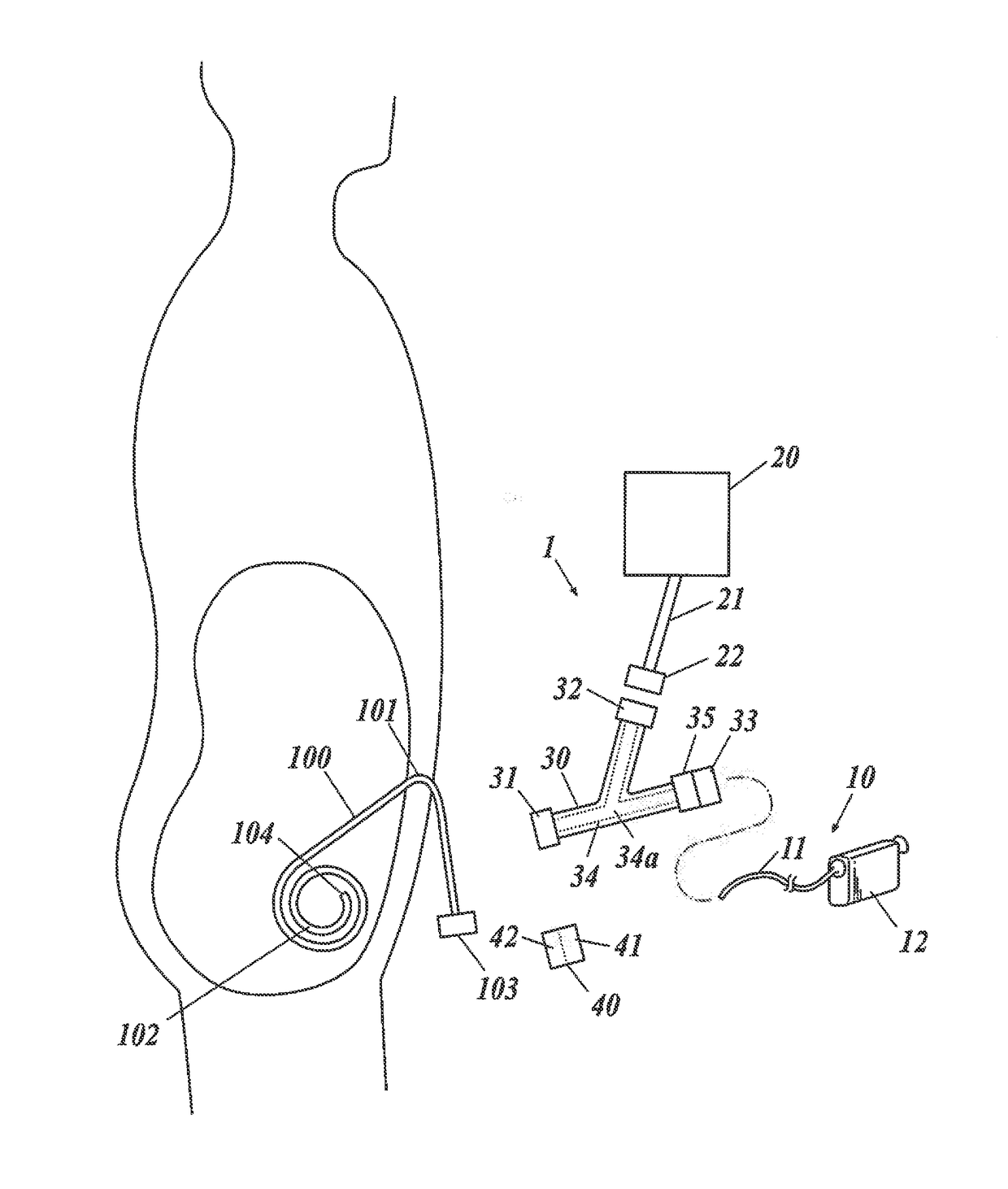
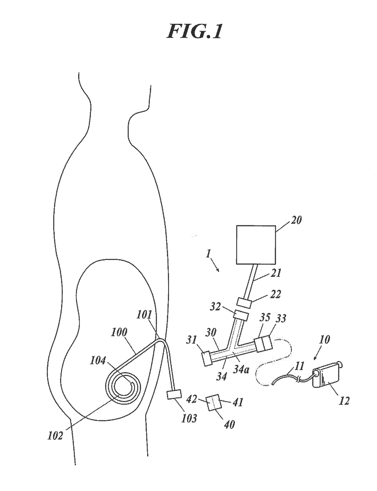
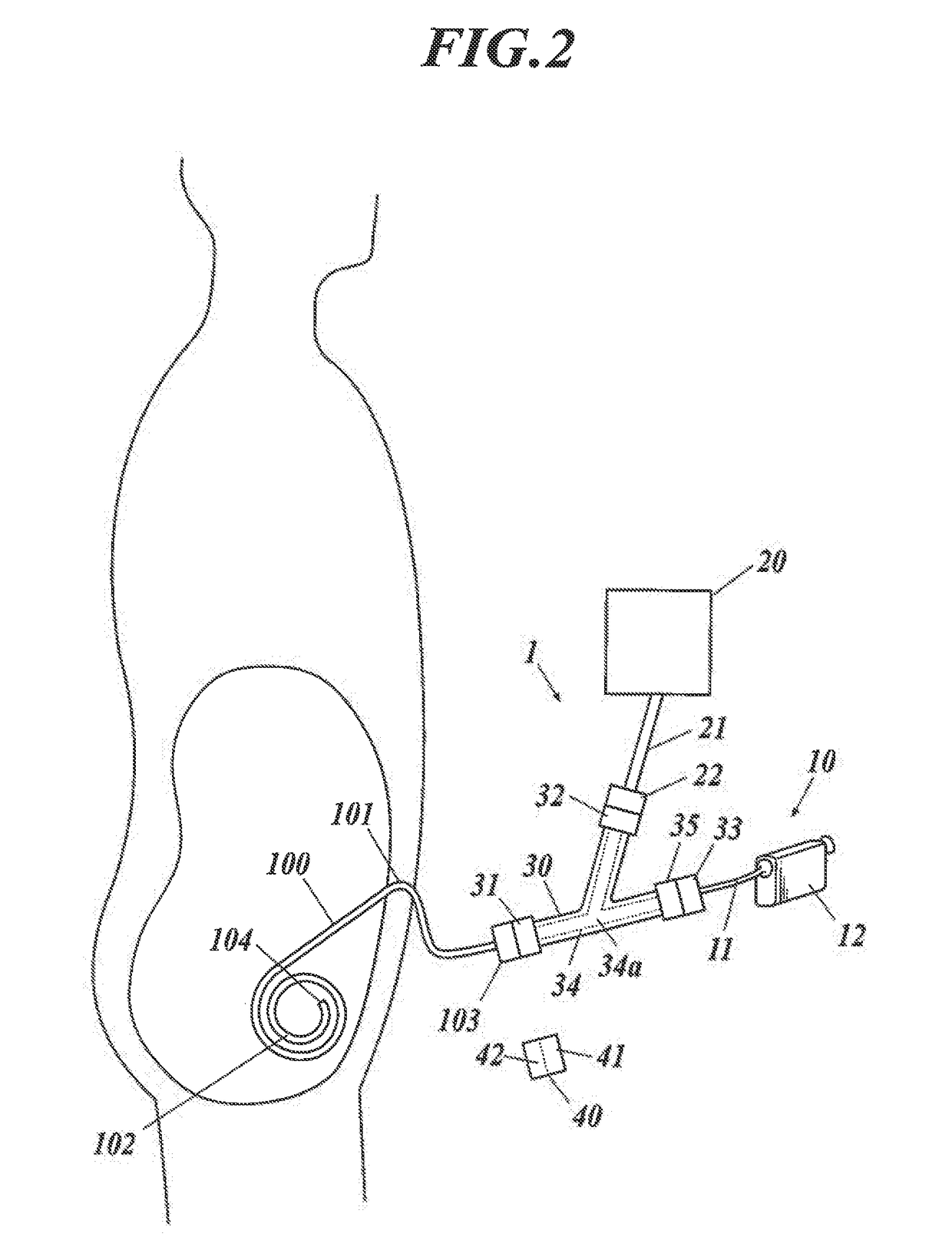
[0131]As illustrated in FIG. 1 to FIG. 3, the endoscopic system 1 of one or more embodiments include an endoscope 10, a fluid feeding means 20 and a joint 30. FIG. 1 illustrates the state in which the joint 30 and the other components are separated from each other. FIG. 2 illustrates the state in which the other components are connected with the joint 30, and the endoscope is inserted. FIG. 3 illustrates the state in which a conversion connector 40 is further connected.

[0132]The endoscope 10 is composed of an insertion part 11 and an operational part 12. The insertion part 11 is composed of an imaging optical system and an illumination optical system, which are covered with a protection tube.

[0133]For the imaging optical system, an imaging lens disposed at the front end of the insertion part ...

embodiment b

[0225]FIG. 1 to FIG. 10C and FIG. 16 to FIG. 30E are referenced in this section.

[0226]Overview of System Configuration

[0227]First, the overview of a whole endoscopic system of one or more embodiments will be described.

[0228]As illustrated in FIG. 1 to FIG. 3, the endoscopic system 1 of one or more embodiments include an endoscope 10, a fluid feeding means 20 and a joint 30. FIG. 1 illustrates the state in which the joint 30 and the other components are separated from each other. FIG. 2 illustrates the state in which the other components are connected with the joint 30, and the endoscope is inserted. FIG. 3 illustrates the state in which a conversion connector 40 is further connected.

[0229]The endoscope 10 is composed of an insertion part 11 and an operational part 12. The insertion part 11 is composed of an imaging optical system and an illumination optical system, which are covered with a protection tube.

[0230]For the imaging optical system, an imaging lens disposed at the front en...


PUM


Abstract

A laparoscopic device includes a flexible insertion part including an imaging optical system and an illumination optical system that are covered with an exterior tube; and an operational part connected to a base end of the insertion part. The insertion part is inserted into a peritoneal dialysis catheter for observation of an abdominal cavity, and the insertion part includes a distal extended part that is extendable from the peritoneal dialysis catheter in the abdominal cavity during use and formed in a shape with a curved part having a cumulative central angle between 180° and 360°.

Description

TECHNICAL FIELD[0001]The present invention relates to a laparoscopic device and an endoscopic system.BACKGROUND ART[0002]To detect an onset of peritonitis or encapsulating peritoneal sclerosis (EPS) in an early stage, which may occur due to peritoneal dialysis, it is effective to periodically observe the condition in the abdominal cavity by means of an endoscope.[0003]However, an abdominal incision is required for introducing a typical endoscope into the abdominal cavity, which brings pain and strain to a patient.[0004]In this regard, an effective method that brings less pain to a patient is to introduce an endoscope into the abdominal cavity by utilizing a peritoneal dialysis catheter that is in use for peritoneal dialysis.[0005]When an endoscope is inserted through a peritoneal dialysis catheter, it is normally difficult to guide the endoscope to a position for observing the great omentum and the small intestine in order to check peritonitis and EPS since the opening of the perito...

Claims


Application Information

Patent Timeline
IPC IPC(8): A61B1/313A61M1/28A61B1/015A61B1/05A61B1/06G02B23/24A61B1/00
CPCA61B1/313G02B23/2461G02B23/2476G02B23/243A61M1/285A61B2090/3966A61B1/05A61B1/0676A61B1/00154A61B1/015A61B2090/3925A61B1/0008A61B1/00071
Inventor MAJIMA, MASANAONATSUNO, YASUYUKIKUNIMOTO, AKIRAFUJIWARA, KATSUMIJONO, JUNICHI
Owner KONICA MINOLTA INC
Why Eureka
Try Eureka