A micro-humidifier

a technology of micro-humidifier and humidifier, which is applied in the direction of inhalators, medical devices, other medical devices, etc., can solve the problems of affecting the humidification effect of respiratory airway and lungs, condensation inside the breathing circuit is a risk factor for ventilator-associated pneumonia, and the relative humidity cannot reach 100% relative humidity, so as to reduce or even prevent condensation, reduce the cost of respiratory humidification, and reduce the occurrence of microbes and mold growth

Inactive Publication Date: 2017-05-25
OUTSTANDING HEALTHCARE COMPANY
View PDF10 Cites 13 Cited by
  • Summary
  • Abstract
  • Description
  • Claims
  • Application Information

AI Technical Summary

Benefits of technology

[0012]Without intending to be limited by theory, it is believed that the new micro-humidifier device developed by the inventors may address one or more of the problems discussed above. Especially, the invention may address existing problems when used in invasive and non-invasive mechanical ventilation. It is believed that the micro-humidifier device and / or the breathing system described herein is capable of supplying gases with various temperature, humidity and / or water droplet sizes. it is believed that the device can reduce or even prevent the occurrence of condensation, reduce microbe and mold growth, and / or lower the cost of respiratory humidification.
[0013]More specifically, and without intending to be limited by theory, it is believed that such a respiratory humidification system and / or micro-humidifier provides surprising benefits such as a reduction or even the prevention of condensation, reduced risk of ventilator-associated pneumonia, reduced energy requirements, reduced system complexity, reduced chance of microbial, and / or mold growth in the respiratory circuit, overall reduced therapy complications and cost, better control over the air humidity and / or temperature actually being inhaled by the patient, etc.
[0014]It is believed that such a small and light micro-humidifier enables the humidification source to be located very close to where the patient breathes in the air from the breathing circuit. This reduces or even eliminates the need for additional heating elements along the inspiratory limb of the breathing circuit, as there is little or no chance for water vapour to condense prior to being inhaled by the patient. This in turn reduces energy required, and also the chances of microbial and / or mold growth. In addition, as the micro-humidifier itself is so close to the patient, it is believed that the micro-humidifier can react more quickly to tidal volume fluctuations and thereby provide improved control of the humidity and / or the temperature of the air inhaled by the patient. Such a system may also allow better control of the quality of the vapour being inhaled by the patient.

Problems solved by technology

Therefore, when the tidal volume increases, the relative humidity typically cannot reach 100% relative humidity because of the air surge.
When relative humidity is less than 100%, the gas condition is not favourable to humidify the patient's airway and lungs; the presence of condensation inside the breathing circuit is a risk factor for ventilator-associated pneumonia.
Both can lead to the occurrence of pneumonia, the failure of the therapy, delay the ventilator weaning process, increase the mortality rate, growth of microbes and mold in condensed water, increased therapy complications and / or cost.
In addition, current humidifying devices, for example, those used in a breathing circuit, employ significant amounts of energy to heat up and evaporate large amounts of water in their humidification chambers.
These devices are also quite heavy and bulky and therefore need to be placed far away from the patient so as not to unduly weigh upon the breathing circuit.
Such a set up also increases the complexity of the system and the amount of energy needed to provide acceptably heated, humid air for the patient to breathe.

Method used


Image

  • A micro-humidifier
  • A micro-humidifier
  • A micro-humidifier

Examples


Embodiment Construction

[0020]Unless otherwise specifically provided, all tests herein are conducted at standard conditions which include a room and testing temperature of 25° C., sea level (1 atm.) pressure, and pH 7, and all measurements are made in metric units. Furthermore, all percentages, ratios, etc. herein are by weight, unless specifically indicated otherwise.

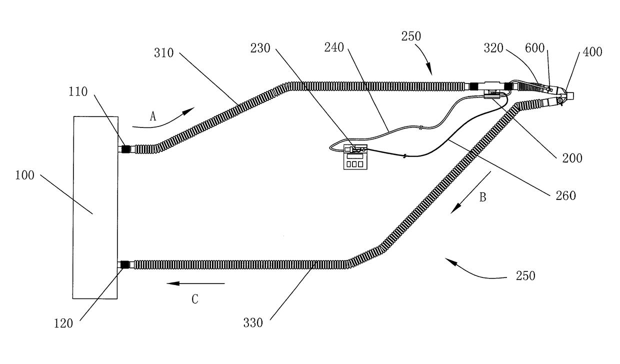
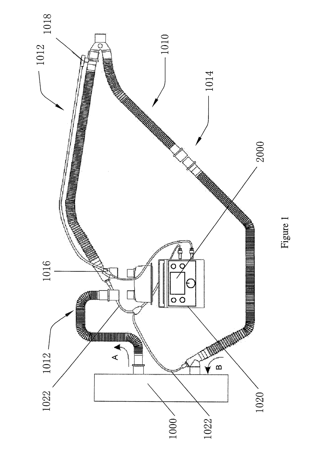
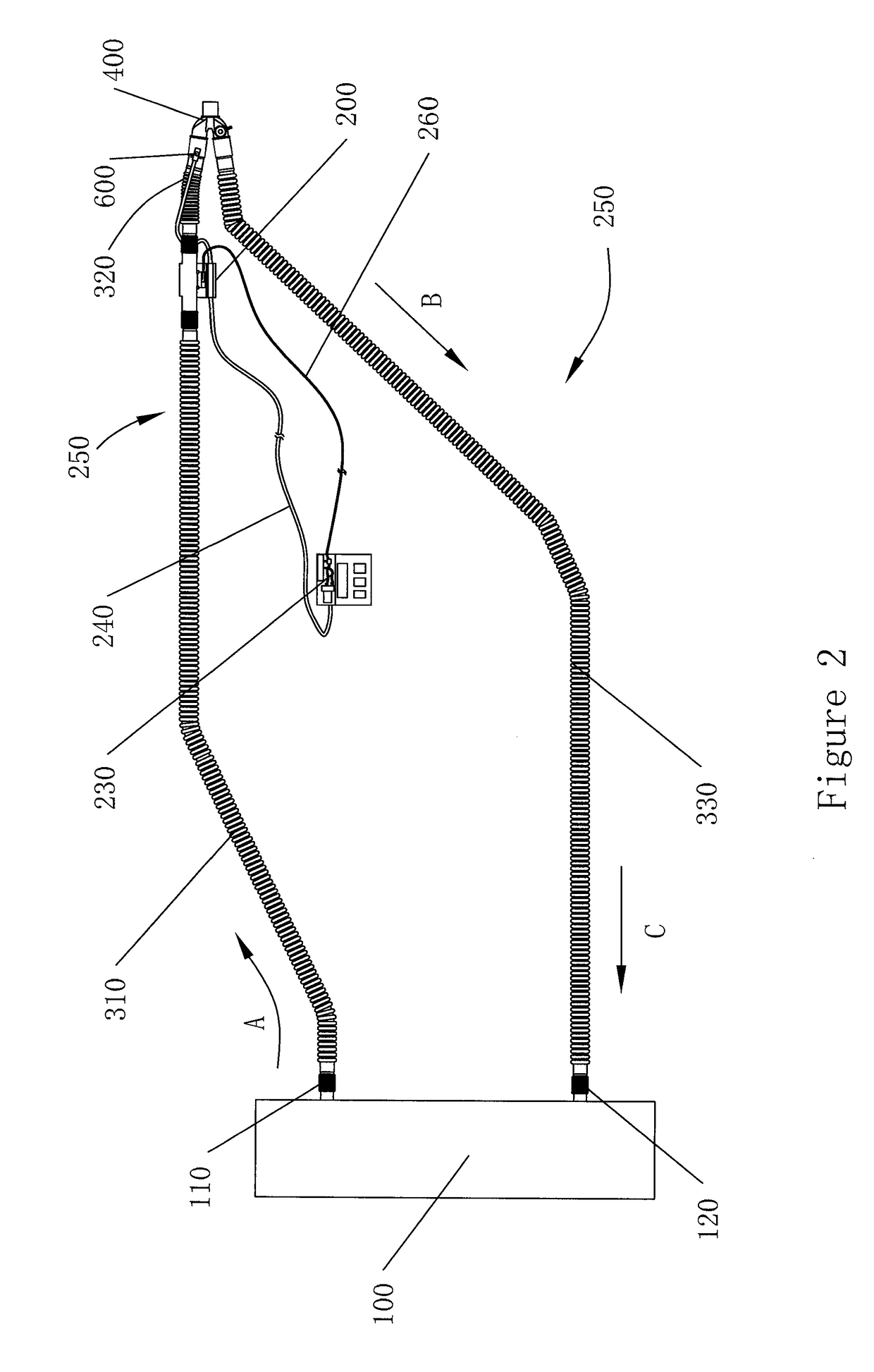
[0021]As used herein, the term “upstream” indicates the direction that the flow (e.g., air flow, liquid flow, etc.) is coming from. Conversely, as used herein, the term “downstream” indicates the direction that the flow is going. In the figures herein, the air flow is indicated with arrows A, B and sometimes C. In these figures, A is always upstream of B which in turn is upstream of C (when present). Conversely, C (when present) is always downstream of B which is in turn downstream of A. In FIG. 4, X is upstream of Y when indicating the direction of the liquid flow.

[0022]As used herein, the term “operably-connected” means that the indicated i...


PUM


Abstract

A micro-humidifier for operably-connecting to a breathing circuit contains a liquid feed, a liquid chamber operably-connected to the liquid feed, and a vapour generator operably-connected to the liquid chamber. The liquid chamber has a volume of from about 0.01 mL to about 30 mL. The micro-humidifier is operably-connected to and/or is designed to be operably-connected to a breathing circuit upstream of the patient. When the micro-humidifier is operably-connected to a breathing circuit, the vapour from the vapour generator enters into the breathing circuit. A respiratory humidification system contains the a breathing circuit and the micro-humidifier as described herein. The micro-humidifier is operably-connected to the breathing circuit upstream of the patient, and the vapour from the vapour generator enters into the breathing circuit.

Description

1. FIELD OF THE INVENTION[0001]A humidifier device may humidify a gas, more specifically humidify a gas delivered to a patient under mechanical ventilation.2. BACKGROUND[0002]Humidifiers are often used in conjunction with, for example, mechanical ventilation systems to assist patients who require humidified air in order to assist their breathing. This may be in a hospital, or at a patient's home.[0003]With mechanical ventilation systems, to prevent the overstimulation and / or damage to the patient's air tract, which may lead to excessive secretions that block the airway, it is sometimes preferred that the gases delivered to patient should be about 37° C. and have a relative humidity of up to 100%. It is also believed that water droplet of appropriate size will have greater chance to deposit in the bronchiole and alveoli[0004]It is further believed that the lung deposition characteristics and efficacy of an aerosol depend largely on the particle or droplet size. Generally, the smaller...

Claims


Application Information

Patent Timeline
Patent Type & Authority Applications(United States)
IPC IPC(8): A61M16/16A61M16/10A61M16/08A61M16/00
CPCA61M16/164A61M16/161A61M16/0051A61M2205/502A61M16/0883A61M2205/3368A61M2016/003A61M16/109A61M15/0085A61M16/16A61M16/162A61M2016/0039A61M2205/505A61M16/022
Inventor ZHENG, ZE GUANGXU, JIE BINGFU, KWOK FUKOH, MING FAITO, KI CHEUNGCHU, CHING SAU
Owner OUTSTANDING HEALTHCARE COMPANY
Why Eureka
Try Eureka