Supercharge Your Innovation With Domain-Expert AI Agents!

Multistage centrifugal pump

a centrifugal pump and multi-stage technology, applied in the direction of pump installation, non-positive displacement fluid engine, liquid fuel engine components, etc., can solve the problems of time-consuming and thus expensive work, and achieve the effect of simplifying the repair and maintenance work and significantly increasing the manufacturing cost of the pump

Active Publication Date: 2017-05-25
GRUNDFOS HLDG
View PDF22 Cites 0 Cited by
  • Summary
  • Abstract
  • Description
  • Claims
  • Application Information

AI Technical Summary

Benefits of technology

This patent describes a design for a maintenance opening in a centrifugal pump. The opening can be closed by a screw-fastened cover, which can also have additional functions. For example, the cover can have a part that passes through the opening and is connected to the seal or bearing, making it easier to examine and repair. The design is particularly useful for inline pumps that have an axial seal at the shaft end. The maintenance opening is advantageously located on the foot part of the pump, and the cover is designed to compensate for hydraulic pressure and wear. Overall, this design simplifies maintenance and repair of the pump.

Problems solved by technology

This work is time-consuming and is thus expensive.

Method used


Image

  • Multistage centrifugal pump
  • Multistage centrifugal pump
  • Multistage centrifugal pump

Examples


Embodiment Construction

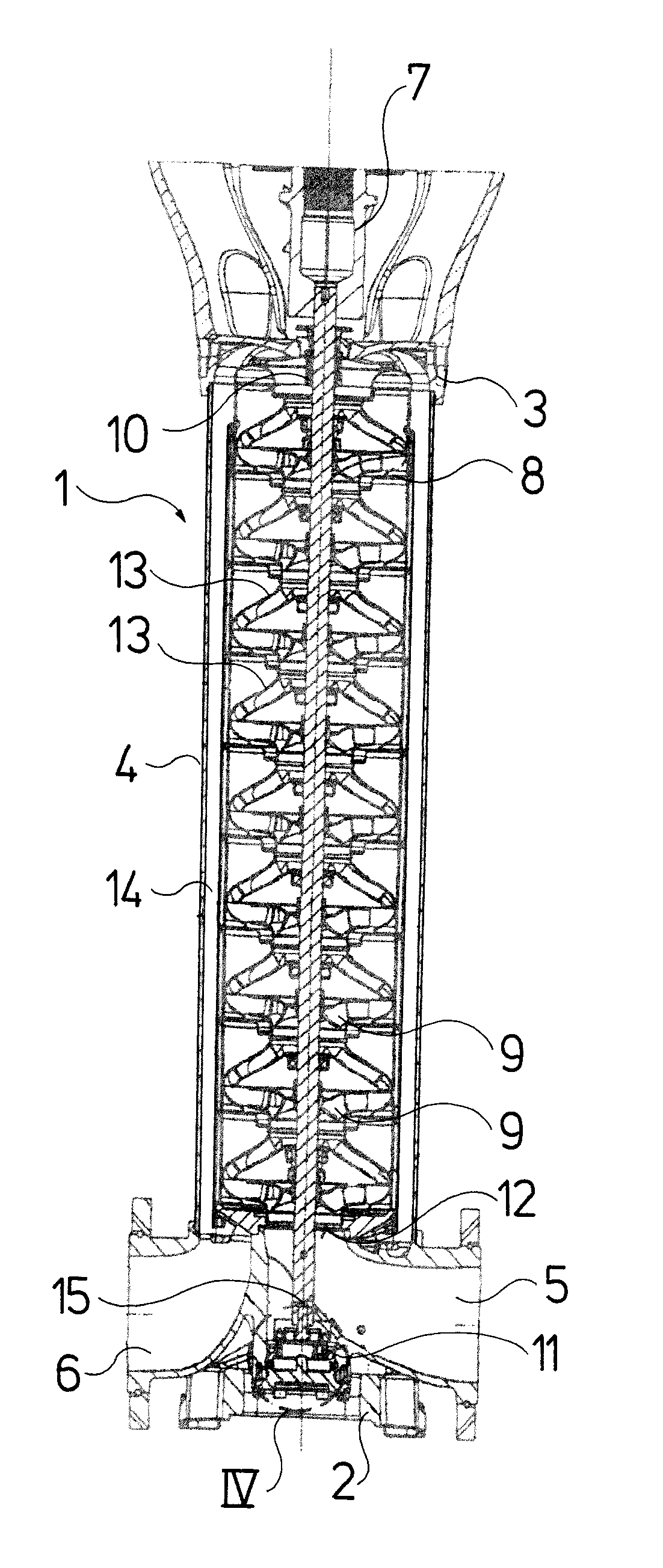
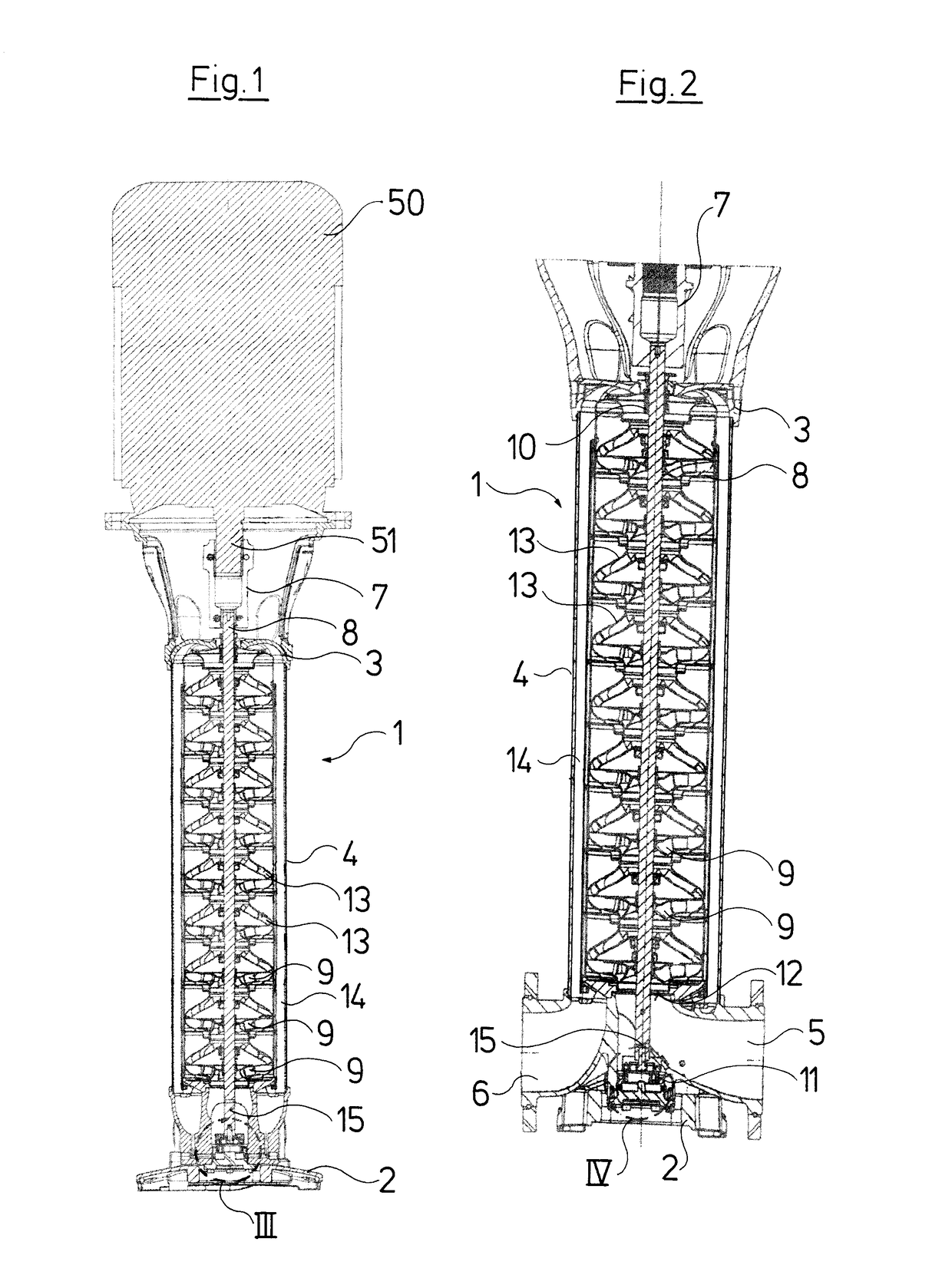
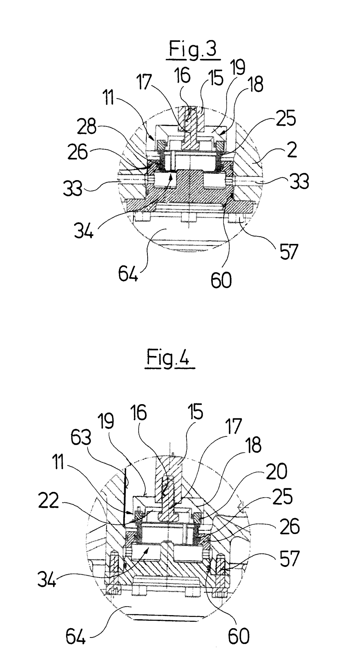
[0028]With the centrifugal pump which is represented by way of FIGS. 1-10 it is the case of a multi-stage centrifugal pump 1 of the inline construction type which is operated in a standing manner. The pump casing comprises a foot part 2, a head part 3 and a cylindrical jacket 4 which is arranged therebetween and which surrounds the pump stages and is clamped between the head part 3 and the foot part 2. The foot part 2 comprises a suction connection 5 as well as, aligned to this, a delivery connection 6. The head part 3 is designed as a motor stool and surrounds a coupling 7 which connects a shaft 51 of an electric motor 50 schematically represented in FIG. 1 and attached on the head part 3, to a shaft 8 of the pump 1 in a rotationally fixed manner. The shaft 8 of the pump 1 carries the impellers 9 of the pump stages and is rotatably arranged within the pump casing. A radial seal 10 is provided in the head part 3, and an axial seal 11 is provided in the foot part 2. The construction ...


PUM


Abstract

A multi-stage centrifugal pump includes a pump casing, in which a shaft (8) carrying an impeller is rotatably arranged. The pump casing has a pump casing foot part (2) that includes a reversibly closable maintenance opening (60), via which a bearing and / or seal (20, 25), which is arranged at a shaft end within the pump casing, is accessible and exchangeable.

Description

CROSS REFERENCE TO RELATED APPLICATIONS[0001]This application claims the benefit of priority under 35 U.S.C. §119 of European Application 15 195 415.3 filed Nov. 19, 2015, the entire contents of which are incorporated herein by reference.FIELD OF THE INVENTION[0002]The invention relates to a multistage centrifugal pump with a pump casing and with a shaft which carries the impellers of the pump stages and which is rotatably arranged within the pump casing.BACKGROUND OF THE INVENTION[0003]Centrifugal pumps of this type and in numerous variants are counted as belonging to the state of the art. In this context, Grundfos pumps (of the Applicant) of the CR series, or Lowara X pumps (of the Xylem concern) of the SV-series are referred to. Such multi-stage centrifugal pumps comprise a common shaft, which carries impellers of pump stages and which is rotatably arranged within a pump casing. Thereby, the drive, in particular with pumps of a larger construction type, is mostly effected via an ...

Claims


Application Information

Patent Timeline
Patent Type & Authority Applications(United States)
IPC IPC(8): F04D29/62F04D13/02F04D17/08F04D25/02F04D29/10F04D29/053F04D29/046F04D29/056F04D29/42F04D1/06F04D29/043
CPCF04D29/624F04D1/06F04D13/02F04D17/08F04D25/02F04D29/043F04D29/628F04D29/046F04D29/056F04D29/4206F04D29/426F04D29/102F04D29/106F04D29/053F04D29/0416F05D2230/72
Inventor SVARRE, ERIK BUNDESENNIELSEN, JOHN FRIGARDSTORGAARD, FINN ULRICHBABAZADEH, IRAJ
Owner GRUNDFOS HLDG
Features
  • R&D
  • Intellectual Property
  • Life Sciences
  • Materials
  • Tech Scout
  • Unparalleled Data Quality
  • Higher Quality Content
  • 60% Fewer Hallucinations
Learn More