Method of manufacturing centrifugal pump

Active Publication Date: 2017-05-25
TERUMO KK
View PDF9 Cites 5 Cited by
  • Summary
  • Abstract
  • Description
  • Claims
  • Application Information

AI Technical Summary

Benefits of technology

[0014]According to the present invention, compression is performed in the direction in which the lid member and the bottom member approach each other in the assembly state, and the lid member and the bottom member are joined. In other words, the lid member and the bottom member are joined in a state where the shaft member is tightened. Accordingly, while the centrifugal pump is in use, whenever the internal pressure in the housing rises and the housing expands in the rotary shaft axial direction, th

Problems solved by technology

Consequently, the shaft member can become misaligned in the vertical direction.
Such oscillation

Method used


Image

  • Method of manufacturing centrifugal pump
  • Method of manufacturing centrifugal pump
  • Method of manufacturing centrifugal pump

Examples


first embodiment

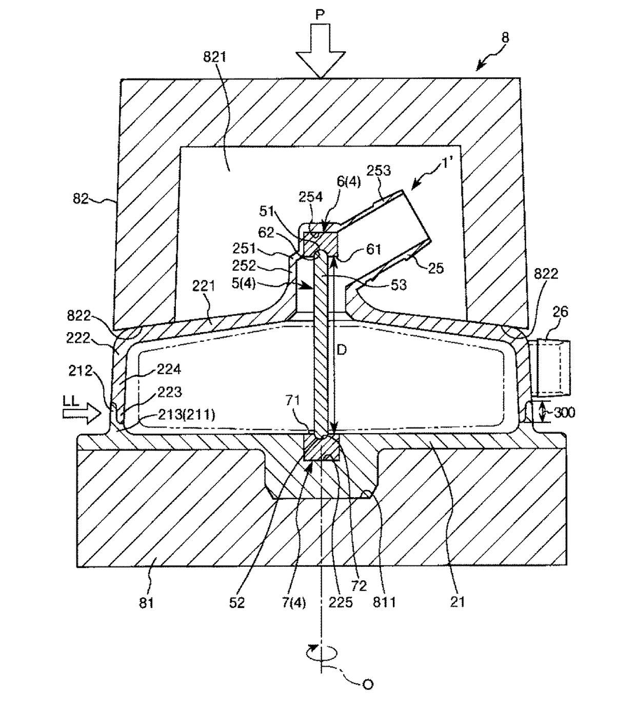
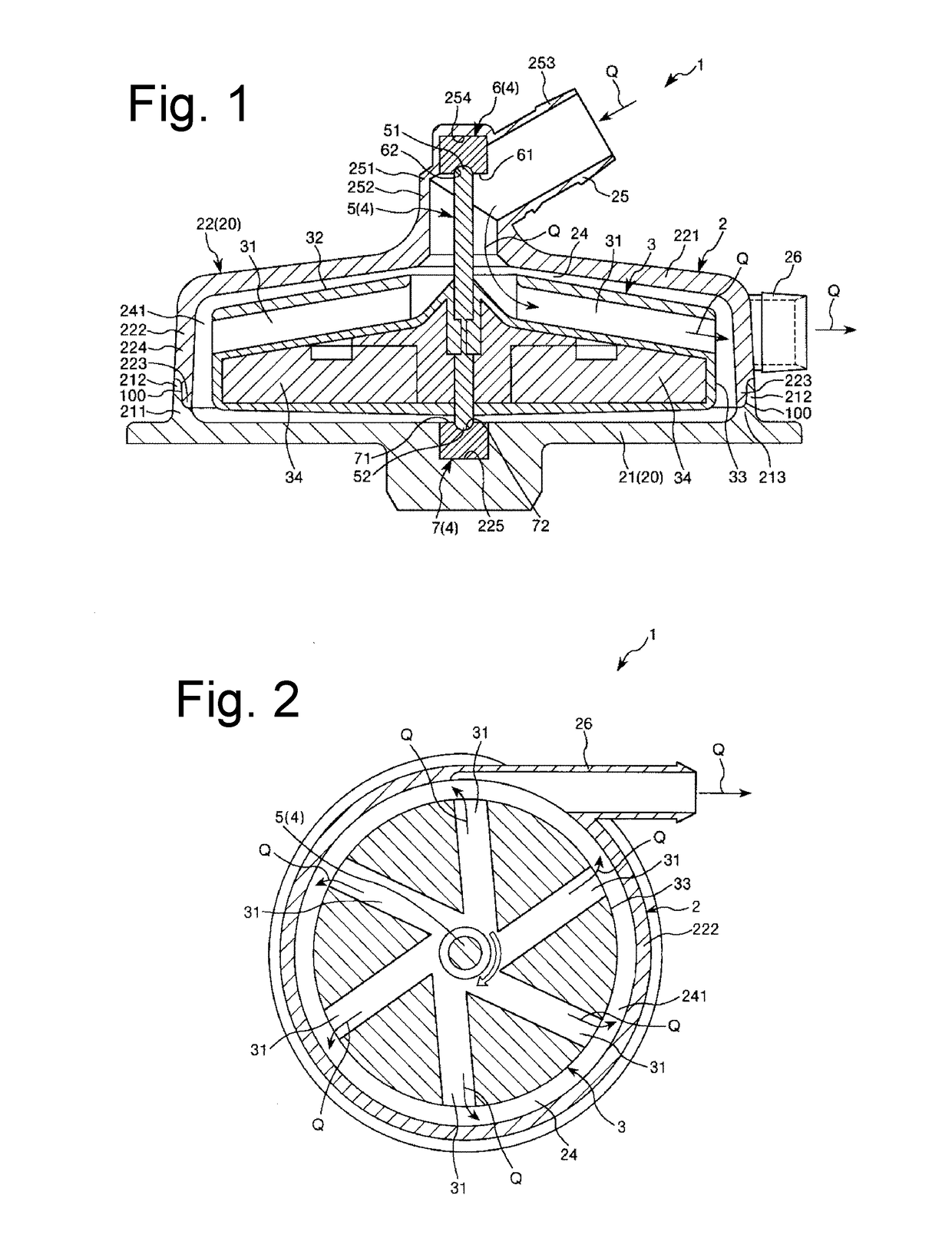
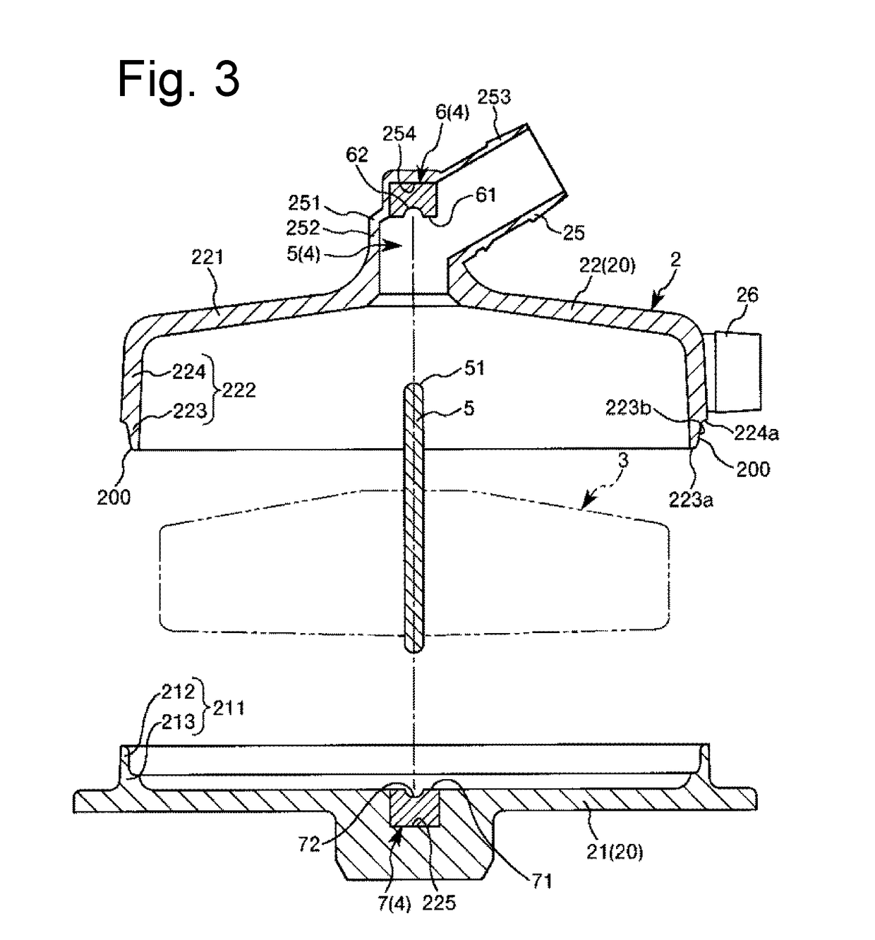
[0021]FIG. 1 is a cross-sectional side view illustrating an embodiment of a centrifugal pump manufactured through a manufacturing method according to the present invention. FIG. 2 is a cross-sectional plan view of the centrifugal pump illustrated in FIG. 1. FIG. 3 is a longitudinal sectional view illustrating a method of manufacturing a centrifugal pump according to the present invention, and the view illustrates a preparing step. FIG. 4 is a longitudinal sectional view illustrating the method of manufacturing a centrifugal pump according to the present invention, and the view illustrates a joining step. FIG. 5 is a longitudinal sectional view illustrating the method of manufacturing a centrifugal pump according to the present invention, and is a partially enlarged view of a housing illustrated in FIG. 3.

[0022]Note that, hereinafter, for convenience of description, in FIGS. 1, and 3 to 5, the upper side will be referred to as “top” or “upward” and the lower side will be referred to ...

example 1

[0090]The centrifugal pump illustrated in FIGS. 1 to 5 was prepared. In this centrifugal pump, the housing (the bottom member and the lid member) and the centrifugal force applying member were formed of polycarbonate. The spring constant of the bottom member was 161 N / mm, and the spring constant of the lid member was 308 N / mm.

[0091]The first bearing and the second bearing were formed of super-high-molecular polyethylene, and the spring constants thereof were 273 N / mm. In addition, the heights of the first bearing and the second bearing in the rotary axis direction were 3.0 mm, the depth of the recessed portion in which the shaft member was inserted was 1.5 mm, and the curvature was 2.0.

[0092]The shaft member was formed of alumina, the outer diameter was 3 mm, and the curvatures of both the end portions were 1.5.

[0093]In addition, in the joining step, compression was performed such that the ratio D1 / D0 between the separation distance D0 and the unhindered separation distance D1 becam...

example 2

[0094]In the joining step, except that compression was performed the according to ratio D1 / D0 indicated in Table 1, a centrifugal pump of Example 2 was obtained in a manner similar to Example 1 described above.


PUM

PropertyMeasurementUnit
Electrical resistanceaaaaaaaaaa
Distanceaaaaaaaaaa
Lightaaaaaaaaaa

Abstract

A centrifugal blood pump prevents a shaft member from oscillating due to expansion of a pump housing resulting from pressurization of the blood. The centrifugal blood pump is manufactured by assembling a bottom member 21 and a lid member 22, and compressing them in a direction in which the bottom member 21 and the lid member 22 approach each other by a deformation amount along their outer circumferential walls. The lid member and the bottom member are joined while in the compressed state in order to create a preloading force between the shaft member and bearings to resist the expansion due to pressurization of the blood during use.

Description

CROSS REFERENCE TO RELATED APPLICATIONS[0001]This application is a continuation of PCT Application No. PCT / JP2015 / 073557, filed Aug. 21, 2015, based on and claiming priority to Japanese application no. 2014-194328, filed Sep. 24, 2014, both of which are incorporated herein by reference in their entirety.BACKGROUND OF THE INVENTION[0002]The present invention relates to a method of manufacturing a centrifugal pump.[0003]In the related art, as blood pumps which transport blood, there have been known turbo-type pumps which send out blood in response to centrifugal force. The turbo-type pump includes a hollow housing, an impeller that is rotatably accommodated in the housing, a rotary shaft (i.e., shaft member) that serves as a rotation center of the impeller, an upper bearing that rotatably supports an upper end portion of the rotary shaft, and a lower bearing that rotatably supports a lower end portion of the rotary shaft (see, e.g., Japanese Patent No. 4548450).[0004]In the blood pump...

Claims


Application Information

Patent Timeline
IPC IPC(8): F04D29/62F04D29/42B23K26/18F04D7/04B23K26/21A61M1/10F04D29/046A61M60/10A61M60/232A61M60/419A61M60/818
CPCF04D29/628A61M1/1013A61M1/1029F04D29/426F04D13/024F04D7/04B23K26/21B23K26/18A61M2207/00F04D29/046F04D29/026F05D2230/234B29L2031/753B29L2031/7496B23K37/0435B29C65/1616B29C65/1635B29C65/1658B29C65/1683B23K26/0823B23K26/324B29C65/7841B29C66/12841B29C66/1286B29C66/543B29C66/65B29C66/71B29C66/73115B29C66/73921B29C66/8322B23K26/282B23K2103/42F04D29/041A61M60/818A61M60/419A61M60/148A61M60/232A61M60/10B29K2027/06B29K2023/06B29K2023/12B29K2025/06B29K2069/00B29K2033/12B29K2067/00B29K2067/003B29K2067/006B29K2081/06
Inventor FURUKAWA, SHINPEI
Owner TERUMO KK
Why Eureka
Try Eureka