Optical strain gauge

a strain gauge and optical technology, applied in the field of optical strain gauges, can solve the problems of high cost of extensometer types, and high rigidity of composite materials

Active Publication Date: 2017-05-25
ILLINOIS TOOL WORKS INC
View PDF7 Cites 16 Cited by
  • Summary
  • Abstract
  • Description
  • Claims
  • Application Information

AI Technical Summary

Benefits of technology

[0013]This disclosure presents a method of measuring the strain response of a test material remotely by optical devices using a thin multi-layer assembly, called an optical strain gauge or OSG, which is attached directly to the test specimen by simply using a pair of adhesive patches built into the assembly. The small planar foil assembly is typically very light, about 1 gram, and adheres flush onto the surface of the test material when attached. The OSG assembly attaches by pressing it onto the specimen by virtue of the two pressure-activated adhesive patches. There is typically no surface preparation necessary for the test specimen. The spatial separation between the two patches adhered to the specimen surface serves to establish an initial gauge length (L) for calculating strain by measuring the stress induced changes to this separation (AL) when a load is applied to the test specimen.

Problems solved by technology

Additionally, with respect to other clip-on extensometers, composite materials are very stiff and tend to break explosively in tensile testing.
This prevents the use of clip-on type of extensometers because they are typically damaged by the forces of the break.
These types of extensometers are expensive, costing thousands of dollars, and are therefore not intended to be single-use devices.
Non-contact optical extensometers, often costing more than $50,000 are typically not able to measure strain to the accuracy necessary to determine correct modulus on such stiff materials.
These steps add up to significant installation labor time for every test.
Additionally, the costs of bare foil strain gauge ranges can be considerable.
Statistically, the preparation steps can be potentially damaging to the specimen material due to, for example, possible effects of the chemicals used and cuts and dings into the specimen.

Method used


Image

  • Optical strain gauge
  • Optical strain gauge
  • Optical strain gauge

Examples


Embodiment Construction

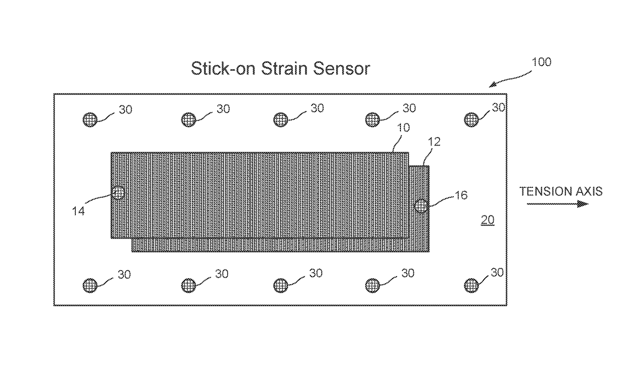
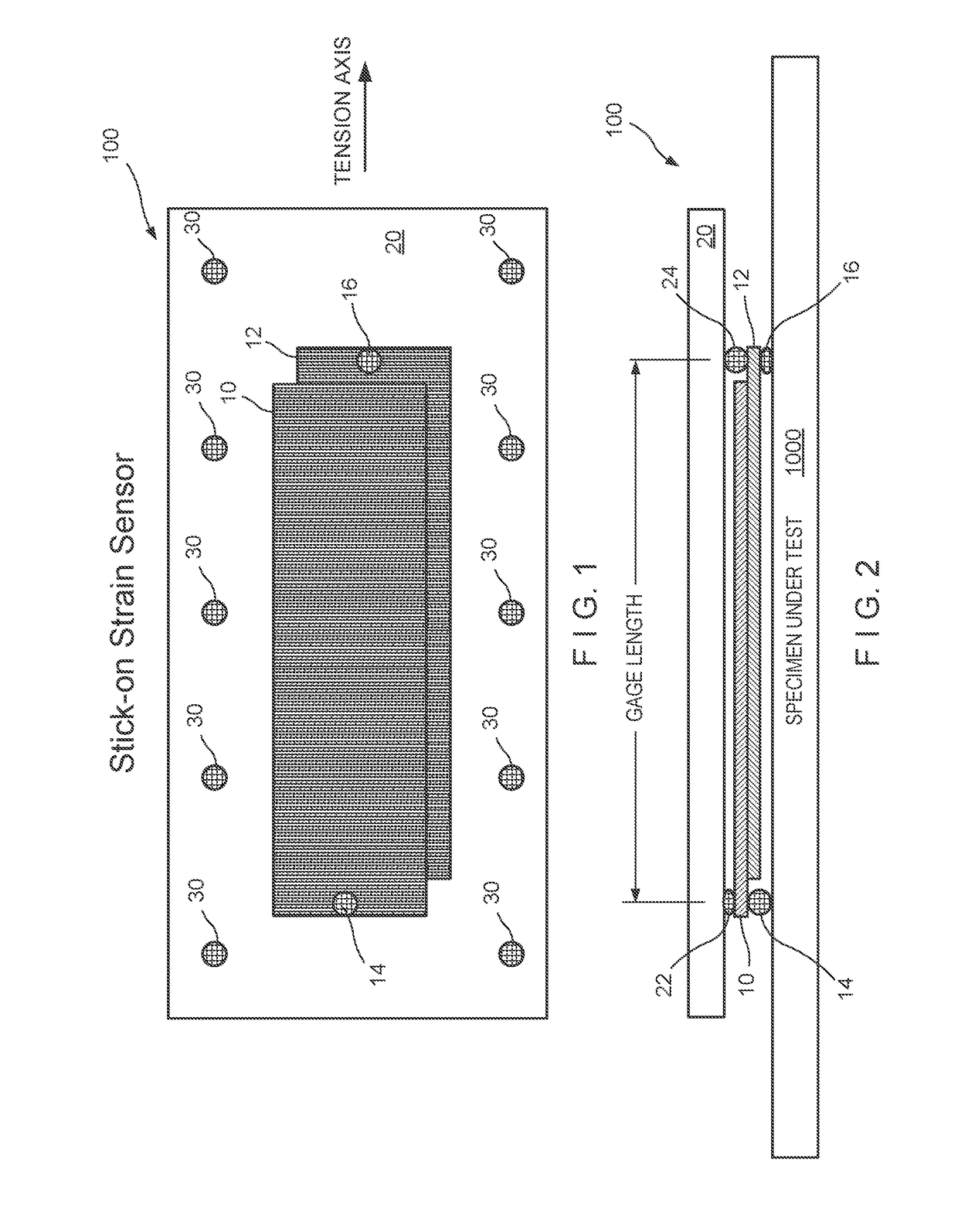
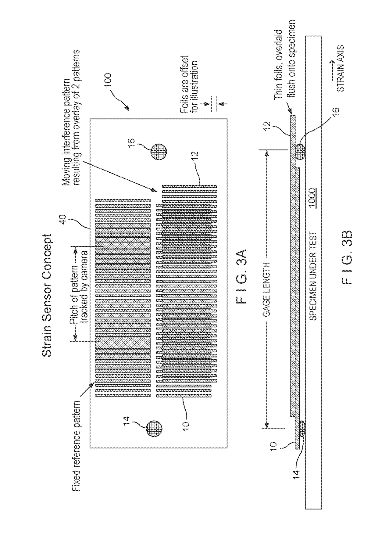
[0030]Referring now to the drawings in detail, wherein like numerals refer to like elements throughout the several views, one sees that FIGS. 1 and 2 illustrate how an embodiment of the multi-layer optical strain gauge assembly 100 works. There is a first grating foil 10 overlapping a second grating foil 12. First and second grating foils 10, 12 may be a polyester substrate having high contrast grating patterns which generate a moire pattern or similar pattern of modulated intensity when overlapped. The first grating foil 10 is attached to the specimen under test 1000 by a first adhesive patch 14. Likewise, the second grating foil 12 is attached to the specimen under test by a second adhesive patch 16. The first and second grating foils 10, 12 are also held in place against transparent compliant layer 20 by third and fourth adhesive patches 22, 24, respectively. The sensor 100 is further held against the specimen 1000 by auxiliary adhesive patches 30 about the periphery of transpare...


PUM


Abstract

This disclosure presents a method of measuring the strain response of a test material remotely by optical devices using a thin multi-layer assembly, called an optical strain gauge, which is attached directly to the test specimen by pair of adhesive patches built into the assembly. The optical strain gauge assembly attaches quickly and easily by just pressing it onto the specimen by virtue of the two pressure-activated adhesive patches. There is typically no surface preparation necessary for the test specimen. The spatial separation between the two patches adhered to the specimen surface serves to establish an initial gauge length for calculating strain by measuring the stress induced changes to this separation when a load is applied to the test specimen.

Description

[0001]This application is a National Phase of International Application No. PCT / US2015 / 034602, filed Jun. 7, 2015, and claims priority under 35 U.S.C. 119(e) of U.S. provisional patent application Ser. No. 62 / 018,071, filed on Jun. 27, 2014, the disclosure of which is hereby incorporated by reference in its entirety, for all purposes, and made a part thereof.BACKGROUND OF THE DISCLOSURE[0002]Field of the Disclosure[0003]The disclosure relates to a method of remotely measuring strain response of a test material by optical methods using a thin multi-layer assembly.[0004]Description of the Prior Art[0005]U.S. Patent Publication No. 2012 / 0176629 A1, entitled “Remote Displacement Sensor, Including an Optical Strain Gauge, an Assembly and System Therewith”, was published on Jul. 12, 2012, based upon PCT / US10 / 048921. This patent application, by the same inventor as the present application, discloses a remote displacement sensor, such as an optical strain gauge, which uses an optical amplif...

Claims


Application Information

Patent Timeline
Patent Type & Authority Applications(United States)
IPC IPC(8): G01B11/16
CPCG01B11/161G01B11/165G01L1/246
Inventor ALLEN, ROY D.
Owner ILLINOIS TOOL WORKS INC
Why Eureka
Try Eureka