

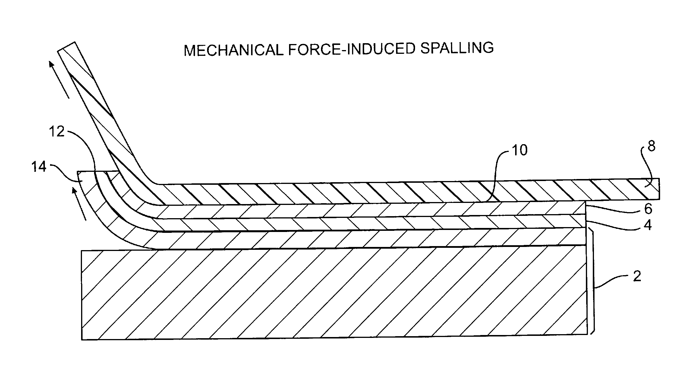
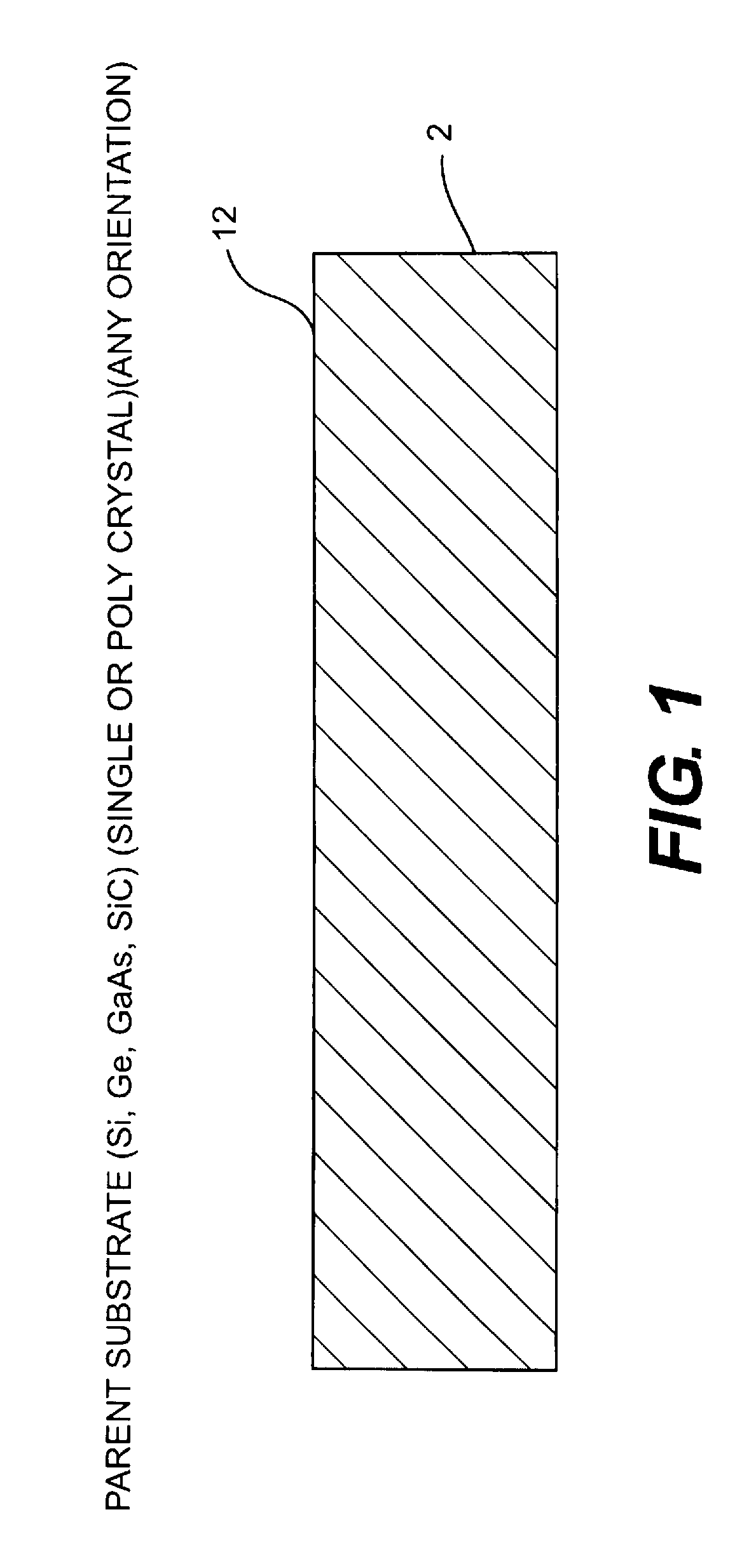
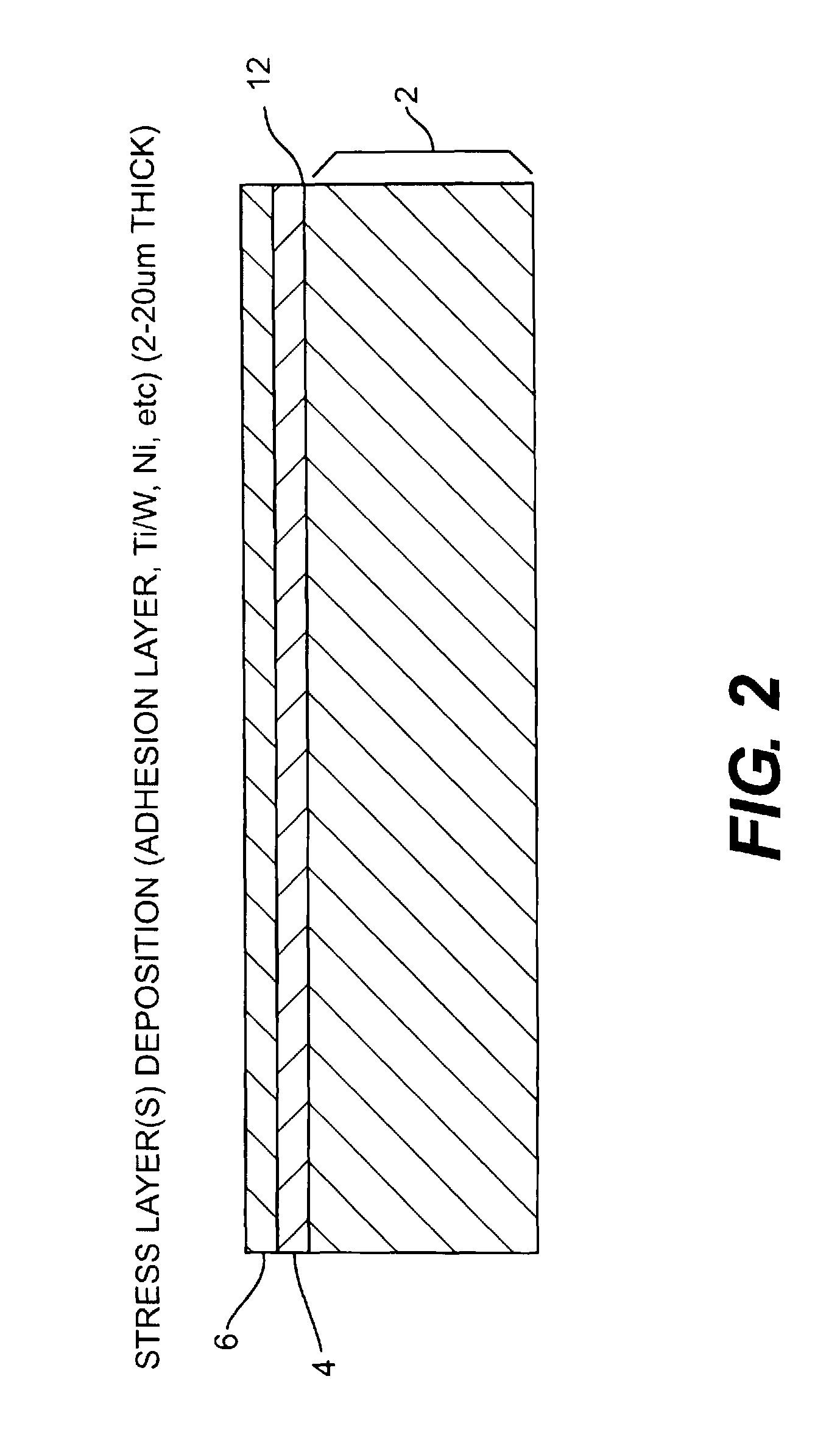
Thin substrate fabrication using stress-induced substrate spalling
a substrate and stress-induced technology, applied in the field of photovoltaic devices, can solve the problems of reducing the efficiency of photovoltaic technology, and increasing the cost of materials, so as to increase the cost per watt value of conventional pv technology, the effect of high efficiency
- Summary
- Abstract
- Description
- Claims
- Application Information
AI Technical Summary
Benefits of technology
Problems solved by technology
Method used
Image

Examples
Embodiment Construction
[0020]To achieve these and other advantages, and in accordance with the purpose of this invention as embodied and broadly described herein, the following detailed embodiments can be embodied in various forms.
[0021]The specific processes, materials compounds, compositions, and structural details set out herein not only comprise a basis for the claims and a basis for teaching one skilled in the art to employ the present invention in any novel and useful way, but also provide a description of how to make and use this invention.
[0022]The invention in one embodiment is a light weight and portable photovoltaic device resistant to humidity, heat, and other outdoor environmental conditions and comprises a thin film direct or indirect bandgap semiconductor active solar cell device (thin film device) positioned on a flexible plastic, i.e., a flexible polymeric material, or other flexible material. This thin film device is further characterized as comprising a single crystal or polycrystalline...
PUM
 Abstract
Description
Claims
Application Information