
Floating Node Reduction Using Random Walk Method

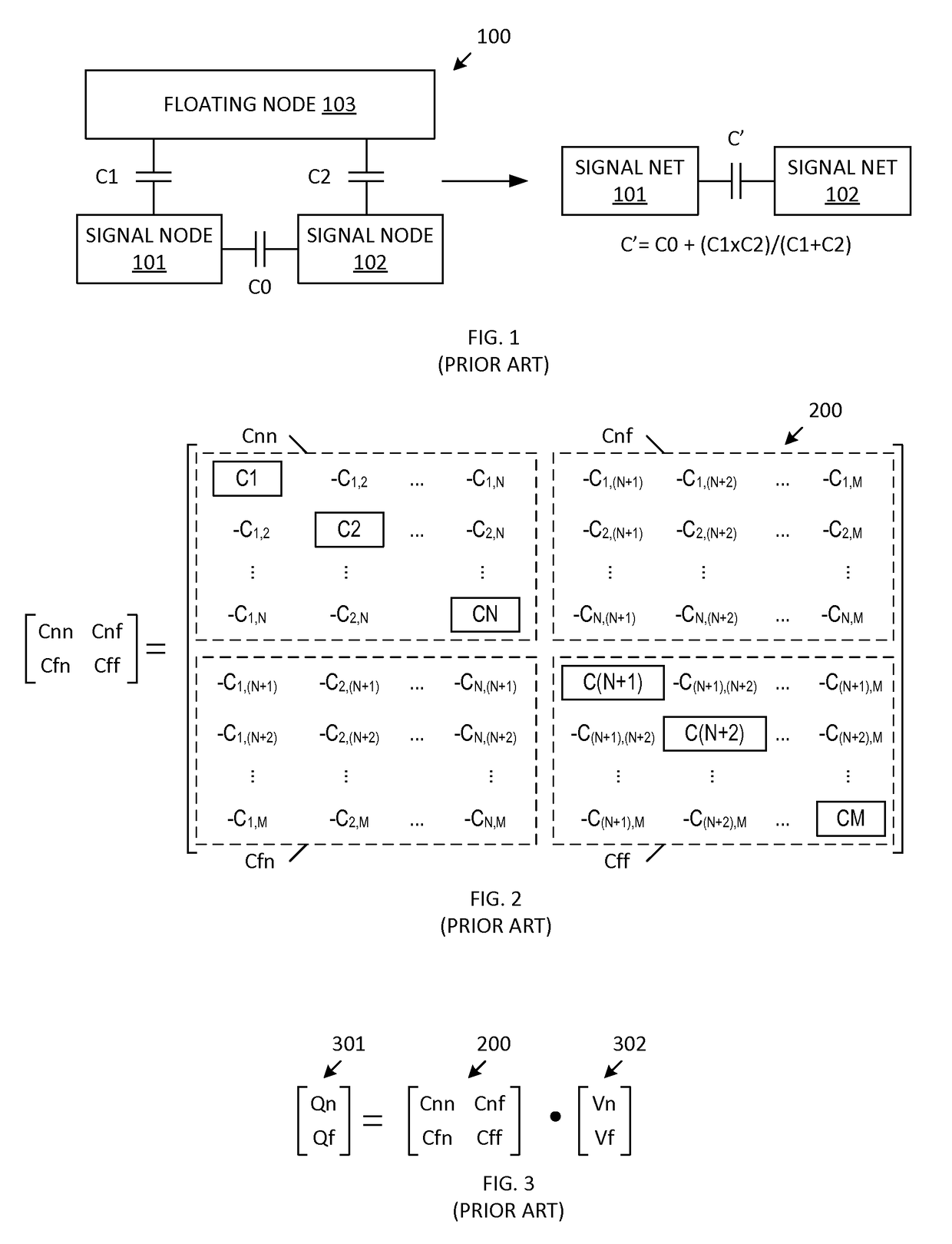
a technology of floating nodes and random walk, applied in the field of floating node reduction in integrated circuit design, can solve the problems of excessive cpu run time required to determine the schur complement matrix, poor performance, and increased difficulty in performing floating node reduction, and achieve the effect of controlling the accuracy of determined indirect coupling capacitances

Active Publication Date: 2017-05-25
SYNOPSYS INC
View PDF3 Cites 3 Cited by
  • Summary
  • Abstract
  • Description
  • Claims
  • Application Information

AI Technical Summary

Benefits of technology

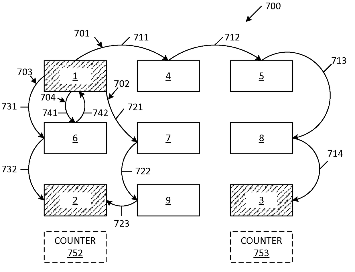
The present invention provides an improved method for reducing floating nodes in an interconnect structure. The method involves performing multiple random walks from a first signal node to a number of associated signal nodes in the interconnect structure. The path of each random walk is determined based on the capacitances of signal nodes and floating nodes. The number of random walks that end on each associated signal node is recorded. The total indirect coupling capacitance of the first signal node is divided among the associated signal nodes based on the number of recorded random walks. The accuracy of the determined capacitances can be controlled by controlling the number of random walks. The method effectively eliminates floating nodes, reducing interference in the interconnect structure.

Problems solved by technology

As interconnect structures become larger and more dense, it becomes more difficult to perform floating node reduction.
If the Schur complement matrix is not sufficiently sparse, the performance becomes poor (i.e., the CPU run time required to determine the Schur complement matrix becomes excessively long).
However, an aggressive sparsification of the Schur complement matrix leads to severe accuracy issues due to rapid error accumulation.
Linear algebra methods for implementing floating node reduction do not provide an acceptable level of accuracy.
Moreover, linear algebra methods will come to a grinding halt when trying to resolve smaller capacitances, and there are currently no other solutions for implementing floating node reduction.

Method used


Image

  • Floating Node Reduction Using Random Walk Method
  • Floating Node Reduction Using Random Walk Method
  • Floating Node Reduction Using Random Walk Method

Examples


Embodiment Construction

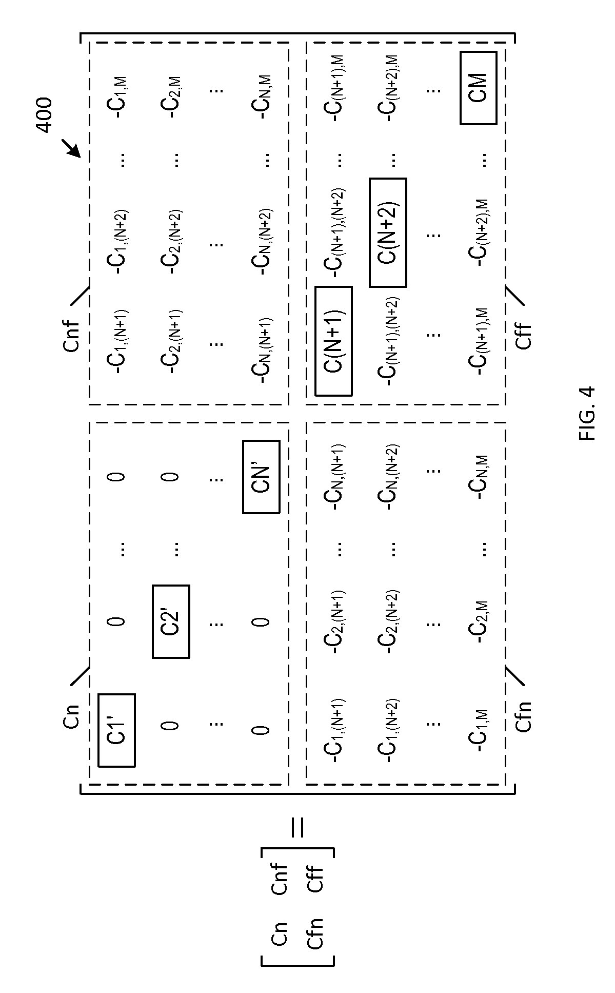
[0027]In general, an extracted capacitance matrix of an interconnect structure is converted into a probability matrix. A plurality of random walks are performed from each signal node of the interconnect structure, using the probability matrix to direct the random walks to other signal nodes (via at least one floating node). The results of the plurality of random walks from each signal node are used to approximate the Schur complement matrix (and thereby implement floating node reduction). The Schur complement matrix is approximated in an accurate and timely manner, thereby overcoming the deficiencies of conventional methods. The present invention will now be described in more detail.

[0028]In the examples described herein, the extracted capacitance matrix 200 (FIG. 2) is converted into a probability matrix in the manner described below. Initially, all of the signal node-to-signal node capacitances between nodes 1 to N are ignored by setting each of these capacitances to a zero value....


PUM


Abstract

A method for floating node reduction uses a capacitance matrix that specifies coupling capacitances between signal nodes and floating nodes of an interconnect structure. Random walks are performed from a first signal node to the other signal nodes, wherein each of the random walks traverses one or more of the floating nodes. Each of the random walks is directed based on probabilities derived from the coupling capacitances of the capacitance matrix. A count is maintained for each of the other signal nodes, wherein each count specifies a number of the random walks that end on the corresponding signal node. The indirect coupling capacitance from the first signal node to a second signal node is selected to correspond with the total indirect coupling capacitance of the first signal node, times the count associated with the second signal node, divided by the total number of random walks.

Description

FIELD OF THE INVENTION[0001]The present invention relates to floating node reduction in an integrated circuit design. More specifically, the present invention relates to the use of a random walk method to implement floating node reduction in an integrated circuit design.RELATED ART[0002]The multi-layer interconnect structures of advanced integrated circuit (IC) designs typically includes signal nets (or signal nodes), which are used to transmit signals / voltages to / from electronic circuitry of the IC, and floating metal fills (or floating nodes), which are not electrically connected to the signal nodes, and which do not carry signals / voltages to / from the electronic circuitry of the IC design. Floating metal fills provide mechanical and structural stability. In general, floating metal fills reduce process variation, which may occur if non-uniform metal density exists in the interconnect structure.[0003]Floating metal fills introduce indirect (parasitic) capacitive coupling between sig...

Claims


Application Information

Patent Timeline
IPC IPC(8): G06F17/50
CPCG06F17/5045G06F17/5068G06F30/327G06F30/39G06F2111/10G06F2119/10G06F30/36
Inventor SVIZHENKO, ALEXEICHATTERJEE, ARINDAMNIEUWOUDT, ARTHUR B.
Owner SYNOPSYS INC
Learn More