Tunnel support installation apparatus

a technology for installing equipment and tunnel supports, which is applied in the direction of shaft equipment, shaft lining, slitting machines, etc., can solve the problems of heavy existing structural support manipulators, difficult for personnel to work safely and comfortably for sustained periods, and disadvantages of conventional mining machine arrangements, etc., to achieve reliable transfer and extend the range of travel

Inactive Publication Date: 2017-06-01
SANDVIK INTELLECTUAL PROPERTY AB
View PDF1 Cites 20 Cited by
  • Summary
  • Abstract
  • Description
  • Claims
  • Application Information

AI Technical Summary

Benefits of technology

[0007]The objectives are provided via the present apparatus in which an extendable roof support manipulator arm and optionally a personnel working platform are movably mounted relative to a fixed base. Accordingly an assembly is provided of reduced weight relative to existing manipulator assemblies that offers a greatly extended range of movement of the manipulator arm. Such an arrangement provides for the efficient and reliable carriage and support of roof and wall lining members. Additionally where the apparatus comprises a working platform personnel are enabled to access a greater range of locations at the raised and forward position of the mining machine in close proximity to the roof and wall where the support members are to be affixed.
[0024]Preferably, the mining machine further comprises a cutting boom pivotally mounted at a mainframe and configured to support and allow a raising and lowering of a rotatable cutting head provided at a forward end of the machine. Preferably, the base is mounted on the mainframe such that the working platform is positionable substantially vertically above the cutting boom and / or the cutting head. The sliding guiderail is advantageous to greatly extend the range of travel of the extendable arm and working platform in the forward and rearward direction by providing a telescopic sliding support arrangement for the arm and working platform. In the fully extended position the guiderail is cantilever mounted at the base via a plurality of guiderail support mounts. Preferably, the apparatus comprises at least two and preferably at least four support mounts positioned approximately at each corner of the base so as to provide an effective cantilever mounting of the guiderail. Accordingly, the weight of the support platform, the extendable arm and working platform may be transferred reliably by a guiderail to the underlying base when moved to it fully forwardmost position.

Problems solved by technology

However, conventional mining machine arrangements are disadvantageous for a number of reasons.
Due to the positional and movement limitations of such personnel working platforms, mounted at the machine, it is often difficult for the personnel to work safely and comfortably for sustained periods.
Existing structural support manipulators are therefore heavy and add considerable load and stress to the machine frame and motor.
In particular, it is not uncommon for parts of the machine frame or components of the motor to crack due to stress concentrations when supporting the considerable mass of the manipulator assembly.

Method used


Image

  • Tunnel support installation apparatus
  • Tunnel support installation apparatus
  • Tunnel support installation apparatus

Examples


Embodiment Construction

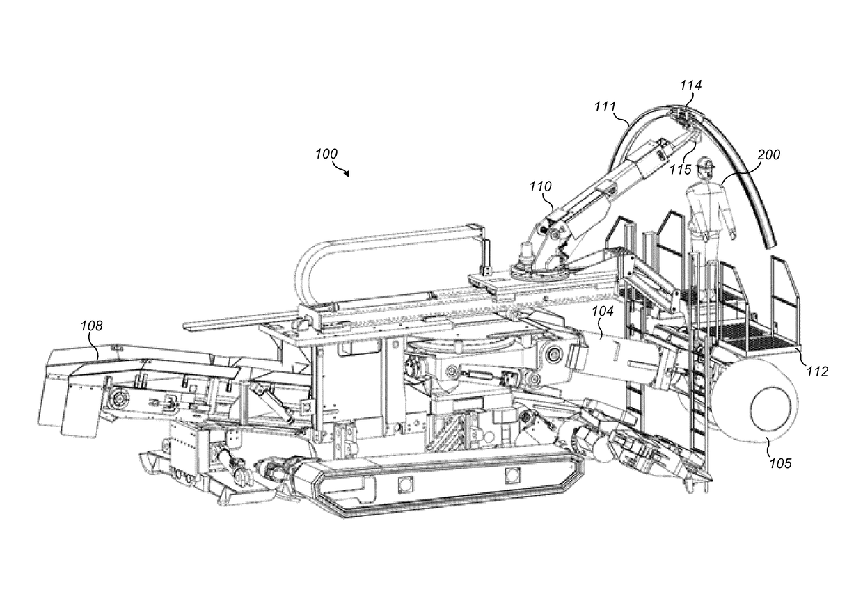
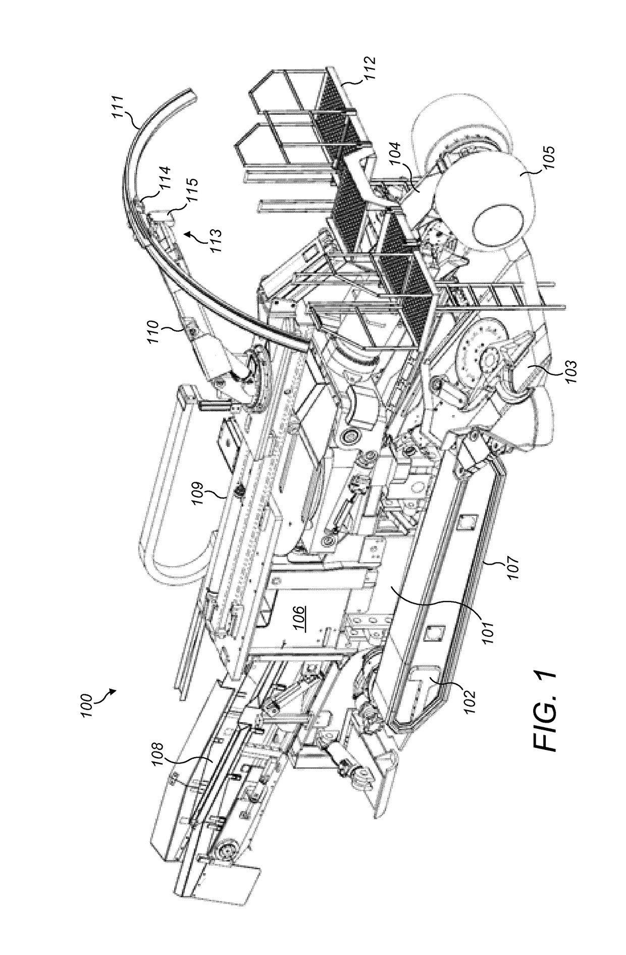
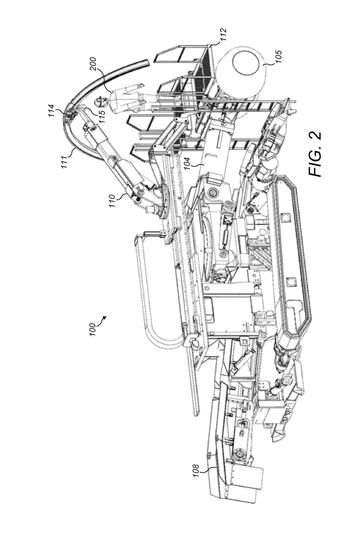
[0035]Referring to FIGS. 1 and 2, a mobile mining machine 100 comprises a mainframe 101 mounting a pair of endless tracks 107 via an undercarriage 102. A motor 106 is also carried by mainframe 101 and is positioned substantially centrally of the main body of machine 100. A rotatable cutting head indicated generally by reference 105 is positioned at a forward end of machine 100 and comprises a plurality of rotating drums that mount a plurality of cutting bits (not shown). Head 105 is mounted at mainframe 101 via an elongate boom 104 that is in turn pivotally mounted at its rearward end to mainframe 101. A gathering head 103 is also mounted at the machine forward end and is positioned below boom 104 so as to receive and gather material dislodged from the cutting face. Machine 100 further comprises a discharge conveyor 108 that extends rearwardly from gathering head 103 and projects rearwardly from the machine 100 behind motor 106.

[0036]Machine 100, typically referred to as a ‘Roadhead...


PUM


Abstract

An apparatus to install structural supports in a mine tunnel is conveniently mountable on a mining machine having a cutting head mounted at one end of a boom. An extendable and slewing manipulator arm of the apparatus is mounted on a support platform that is slidable in the axial forward and rearward direction and includes a grasping device to hold the structural supports in a plurality of different positions.

Description

FIELD OF INVENTION[0001]The present invention relates to apparatus to install structural supports in a mine tunnel and in particular, although not exclusively, to a mining machine mounted assembly having an extendable arm to transport and hold the supports for attachment to the tunnel roof or walls.BACKGROUND ART[0002]Mobile mining machines have been developed to provide both direct cutting at the rock face and rapid road and tunnel development within the mine. Typically, a mobile tunnel development machine comprises a rotatable cutting head having bits provided on rotating drums to break the rock face. The cutting head is mounted at a movable boom to create the tunnel with the desired width and height. As the cutting head is rotated and advanced into the face, extracted material is gathered by a gathering head and conveyed rearwardly via machine mounted conveying apparatus.[0003]To secure the tunnel as the mining machine is advanced, it is common to support the roof and walls with ...

Claims


Application Information

Patent Timeline
Patent Type & Authority Applications(United States)
IPC IPC(8): E21D11/40E21D11/18E21C27/24
CPCE21D11/403E21C25/10E21D11/18E21C27/24
Inventor STEC, JANSOCHA, MAREK
Owner SANDVIK INTELLECTUAL PROPERTY AB
Why Eureka
Try Eureka