Magnetic field detection sensor

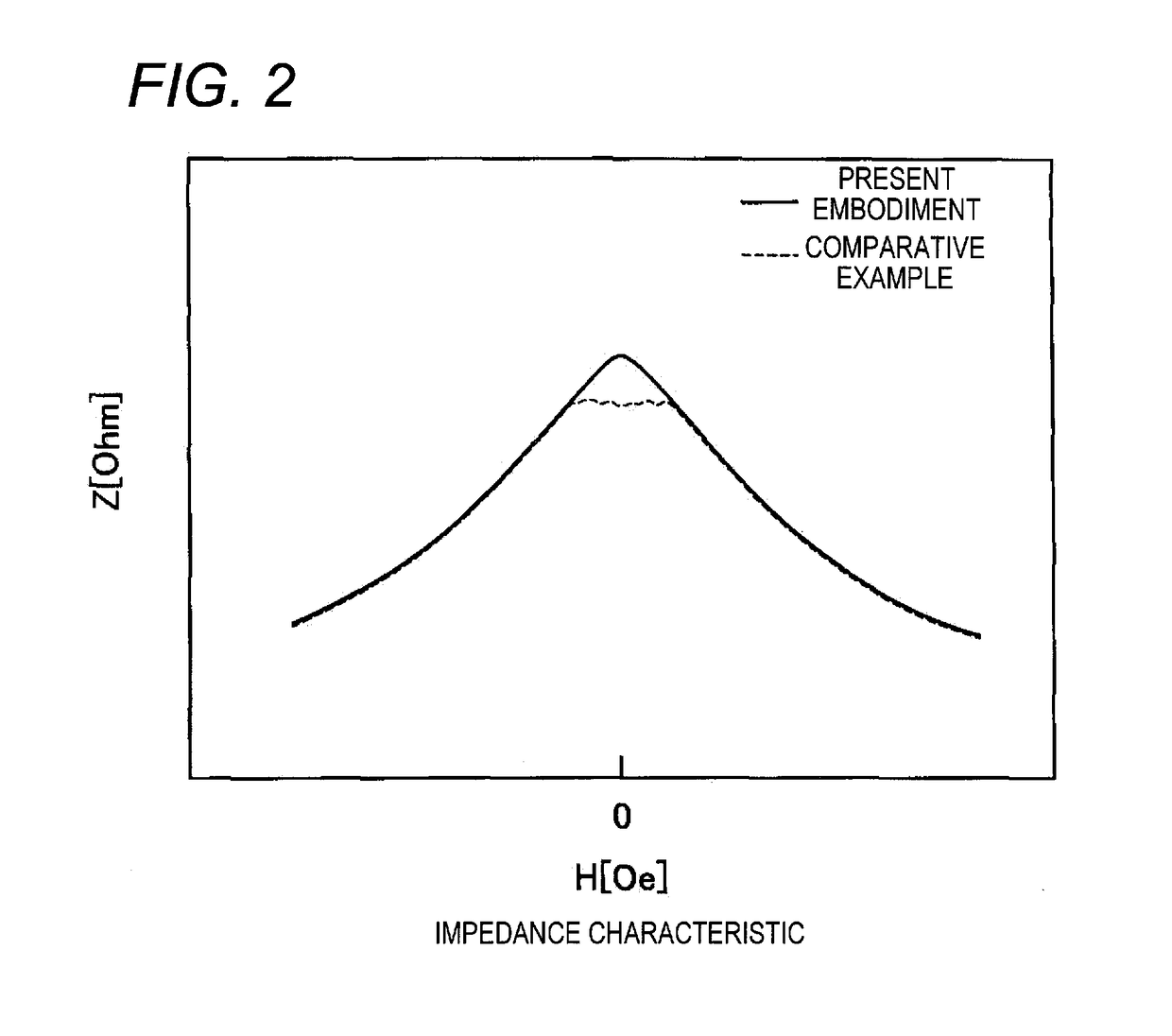
a magnetic field and detection sensor technology, applied in the direction of magnetic measurements, instruments, measurement devices, etc., can solve the problems of disordered impedance characteristic, difficult to make an mi element, and difficult to make an impedance characteristi

Active Publication Date: 2017-06-01
YAZAKI CORP
View PDF17 Cites 0 Cited by
  • Summary
  • Abstract
  • Description
  • Claims
  • Application Information

AI Technical Summary

Benefits of technology

[0011]According to the magnetic field detection sensor of the second aspect, since the magnetic impedance element is attached to one surface of the bus bar and the magnet is attached to the other surface of the bus bar, the positional relationship therebetween is made fixed by the bus bar, whereby it is possible to prevent a situation that a magnetic field can not be generated in the thickness direction of the magnetic thin film because of breakage of the positiona...

Problems solved by technology

However, it is not easy to make an MI element so that the impedance characteristic is such as to monotonously decrease with the zero magnetic field as the peak as described in JP-A-2001-116814, JP-B-4016750, and JP-A-2015-92144, and there are cases where the impedance characteristic is disordered in the vicinity of the peak of the zero magnetic field and ...

Method used


Image

  • Magnetic field detection sensor
  • Magnetic field detection sensor
  • Magnetic field detection sensor

Examples


Embodiment Construction

[0015]Hereinafter, the present invention will be described in line with a preferred embodiment. The present invention is not limited to the embodiment shown below and may be modified as appropriate without departing from the gist of the invention. Moreover, while there are parts where illustrations and descriptions of some components are omitted in the embodiment shown below, it is to be noted that regarding details of the omitted technology, a publicly known or well-known technology is applied as appropriate within the bounds of not being inconsistent with the contents described below.

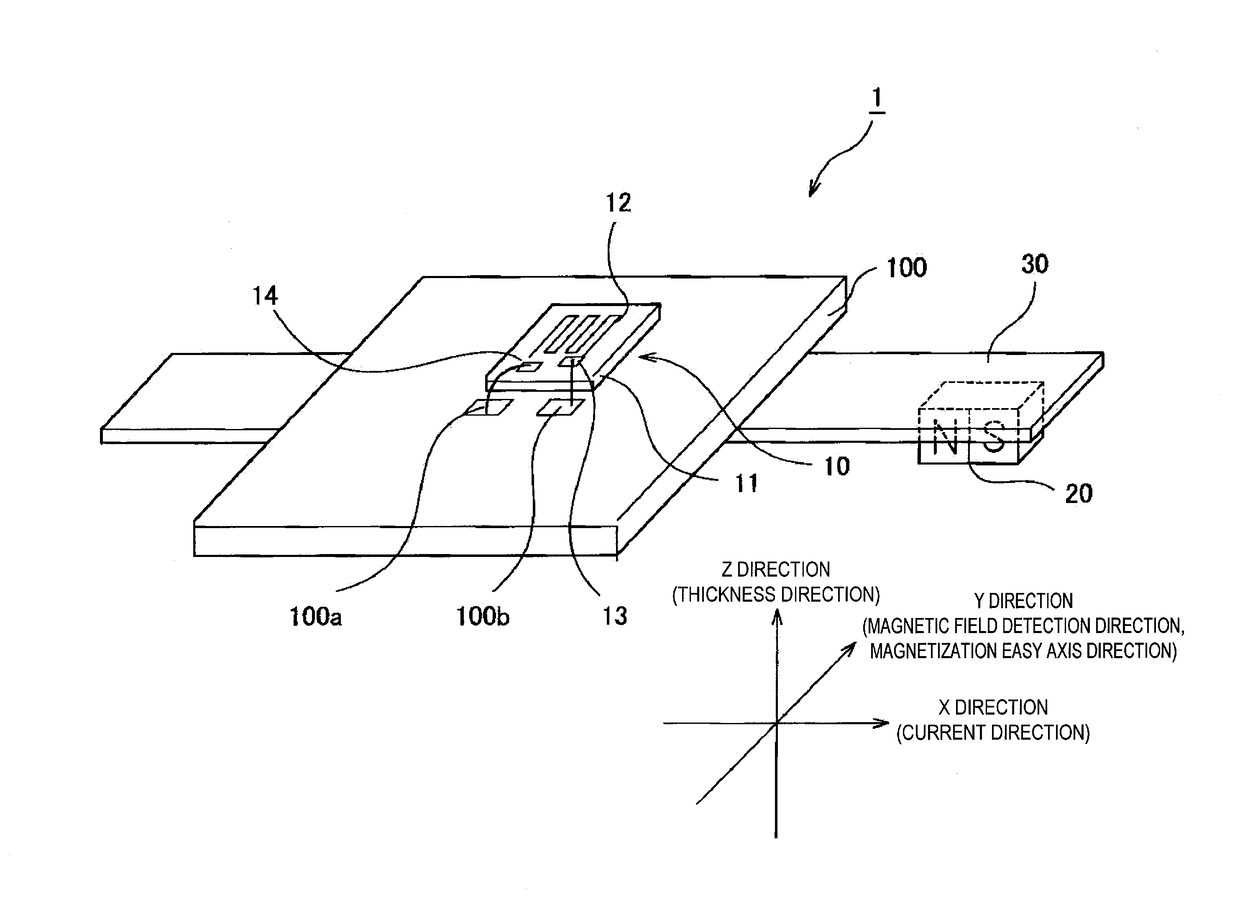
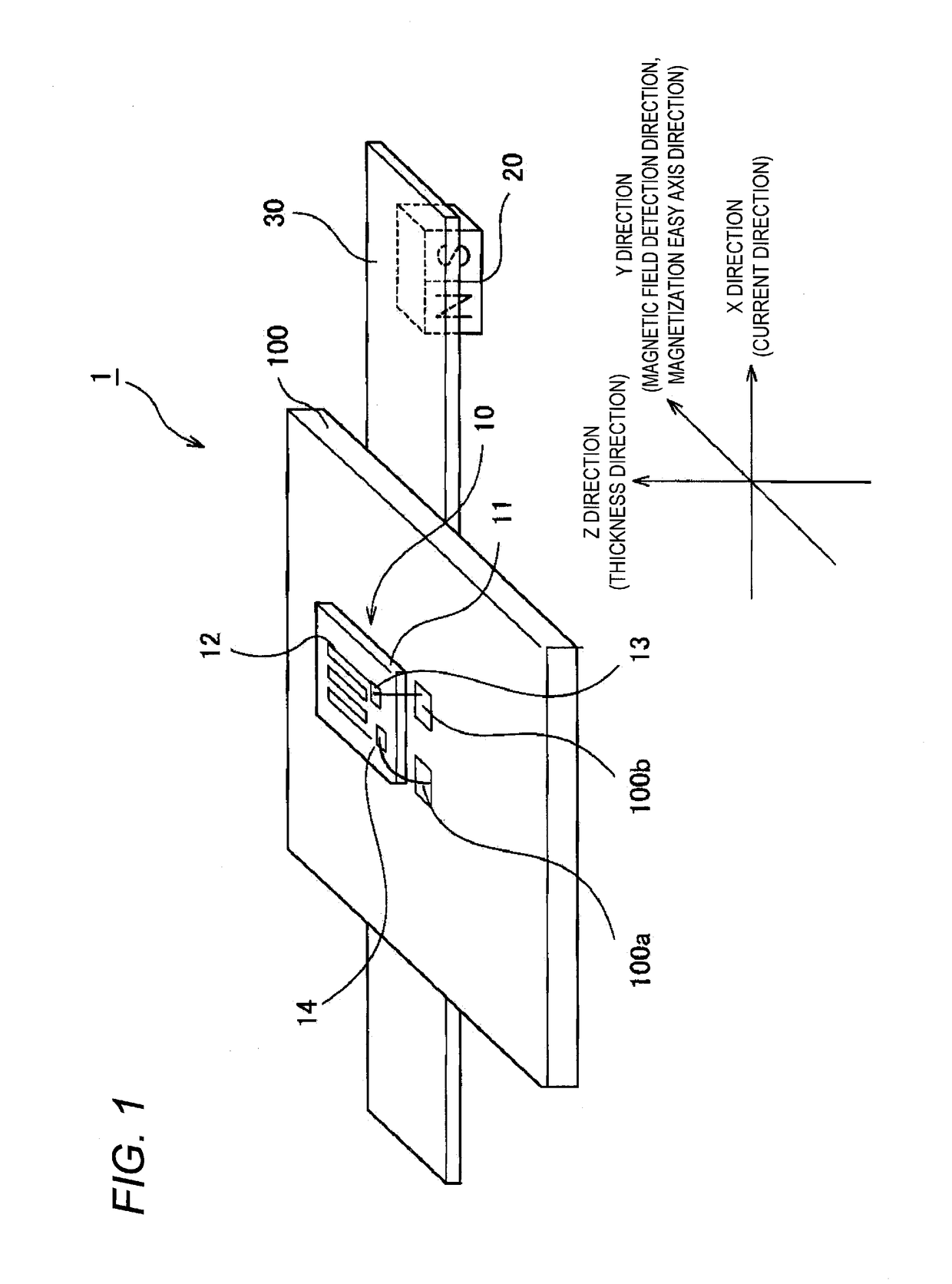
[0016]FIG. 1 is a structural view of a magnetic field detection sensor according to the present embodiment. While an example in which the magnetic field detection sensor is used as an element of a current sensor is described in the example shown in FIG. 1, the magnetic field detection sensor is not necessarily used as an element of the current sensor but may be used as an element of a direction sensor...


PUM


Abstract

A magnetic field detection sensor includes a magneto-impedance element and detects an external magnetic field from an output obtained by applying alternating current to the magneto-impedance element using a magneto-impedance effect. The magneto-impedance element includes a non-magnetic board and a magnetic film formed on a surface of the non-magnetic board, a longitudinal direction of the magnetic film is set as a detection direction of the external magnetic field, and magnetic anisotropy is provided such that a magnetization easy axis of the magnetic film is the same as the detection direction of the external magnetic field. The magnetic field detection sensor further includes a magnetic field generating portion which generates a magnetic field in a thickness direction of the magnetic film.

Description

CROSS-REFERENCE TO RELATED APPLICATION(S)[0001]This application is based on and claims priority from Japanese Patent Application (Application No. 2015-230417) filed on Nov. 26, 2015, the entire contents of which are incorporated herein by reference.BACKGROUND[0002]1. Field of the Invention[0003]The present invention relates to a magnetic field detection sensor.[0004]2. Description of Related Art Conventionally, for example, a magnetic field detection sensor has been proposed that is provided with an MI (magneto-impedance) element using an magneto-impedance effect. This magnetic field detection sensor may be applied, for example, as a current sensor that is disposed adjacent to an electric wire or the like where current to be measured flows and measures the current value by detecting the magnetic field generated by the current flowing on the electric wire or the like.[0005]Moreover, as such a magnetic field detection sensor, a sensor has been proposed where the MI element is made so ...

Claims


Application Information

Patent Timeline
IPC IPC(8): G01R33/06
CPCG01R33/063
Inventor SUGIYAMA, HIROKITANIGAWA, JUNYAISHII, MAKOTOSHOUDA, TAKAHIRO
Owner YAZAKI CORP
Why Eureka
Try Eureka