Louvered separator

a technology of loud separator and separator plate, which is applied in the field of loud separator plate, can solve the problems of not being able to consider filtering fabrics or other jackets, destroying devices quickly, and water separation profiles that do not work flawlessly, so as to reduce the size and power of the blower required for air intake, improve water separation capacity, and reduce pressure loss

Active Publication Date: 2017-06-08
ALUPRO
View PDF4 Cites 3 Cited by
  • Summary
  • Abstract
  • Description
  • Claims
  • Application Information

AI Technical Summary

Benefits of technology

[0024]The louvered water separator according to the invention has considerable advantages over the prior art. Based on the tests and calculations performed, the pressure loss factor decreases from an approximate value of 12 to a value of 3 as compared to the corresponding prior louvered separators. As the pressure losses are significantly lower, the size and power of the blowers required for air intake can be reduced accordingly. Also, the water separating capacity is better than with prior structures, whereby smaller devices requiring less power provide intake air that contains less water.

Problems solved by technology

Particularly in ships, oil platforms and similar marine conditions, the combustion air taken for engines and the fresh air taken for air conditioning devices contains so much water that, as such, it would quickly destroy the devices.
Due to large amounts of air, any filtering fabrics or other jackets may not be considered because of high pressure losses.
However, there are some drawbacks in the prior art.
The water separating profiles do not work flawlessly because the water-collecting troughs therein give rise to rough vortices within the air flow which mix the air flow and thus cause significant pressure losses.
The vortical motion of the flow also produces an uncontrolled flow of the droplets.
Thus, a large amount of the water droplets are able to pass through the water separator, unless the separating channels are made long and extremely staged in such a way that a sufficient total separating capacity will be reached, which again leads to significant pressure losses.
Thus, in the known water separators the separating capacity and pressure losses are both of an unsatisfactory level.

Method used


Image

  • Louvered separator
  • Louvered separator
  • Louvered separator

Examples


Embodiment Construction

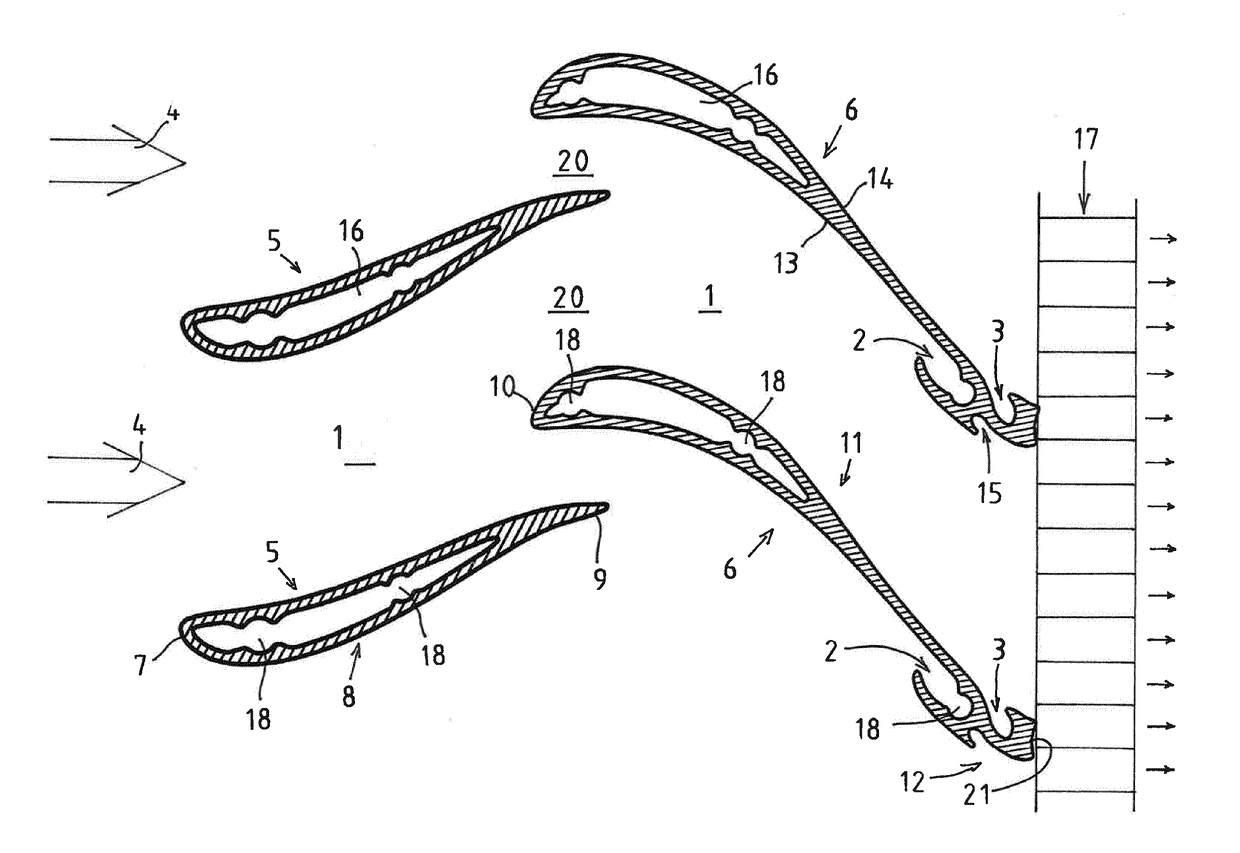
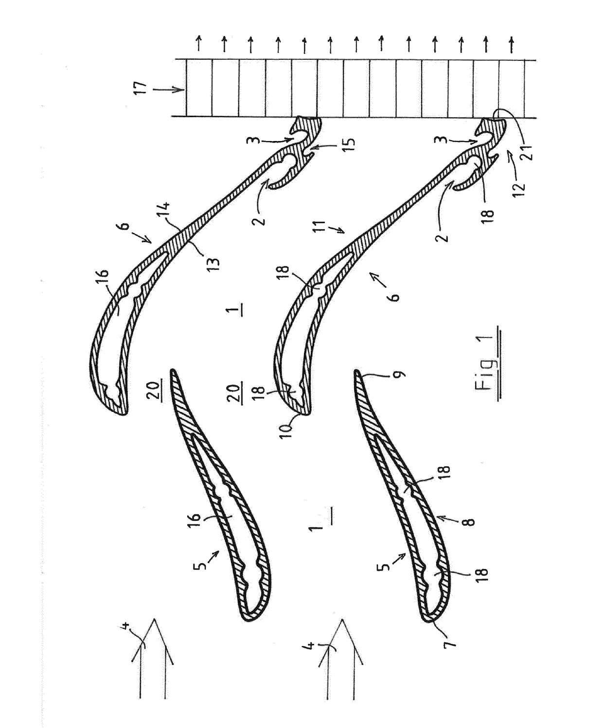
[0026]FIG. 1 illustrates a small part only of one plane louvered separator according to the invention, i.e., as seen from above or below, the profiles of two adjacent slat structures and the corresponding part of a rectifier 17 provided, in a flow direction 4, behind the profiles. A complete louvered separator may practically contain several tens of such identical adjacent slat structures, the slat structures being up to several meters long and the rectifier extending through the entire surface area delimited by the slats, i.e. through their total height and width.

[0027]The slat structure illustrated in FIG. 1 consists in this invention of two separate slats, a front slat 5 and a back slat 6. The air flow direction 4 through the louver is from left to right in the figure. The front slat 5 that is shaped as an airfoil is circular at a leading edge 7, increasing in its thickness and slightly curving, in the flow direction, to the left, i.e. in a first direction. The front slat is thic...


PUM

PropertyMeasurementUnit
lengthaaaaaaaaaa
distancesaaaaaaaaaa
areaaaaaaaaaaa

Abstract

The invention relates to a louvered separator for separating water from an air flow. The louvered separator comprises a number of vertical slat structures having a constant profile, horizontally spaced from each other so as to form horizontally tortuous separating channels (1) in the spaces between the slats. The slat structures are provided with water-collecting troughs (2,3). The slat structure comprises two separate slats having differing constant profiles; in the air flow direction (4) a foremost front slat (5) and a following back slat (6). The front slat comprises, in the flow direction, a leading edge (7), a middle area (8) and a trailing edge (9), and the back slat comprises, in the flow direction, a leading edge (10), a middle area (11) and a trailing edge (12). According to the invention, the water-collecting trough (2,3) is limited to the area of the trailing edge (12) of the back slat (6), so that the front slat (5) entirely, and the back slat (6) for more than a half of its length from the leading edge (10) towards the trailing edge (12), form only even surfaces to guide the flow.

Description

FIELD OF THE INVENTION[0001]The invention relates to a louvered water separator for separating water from an air flow in connection with different types of air intake openings, such as in connection with engines and air conditioning devices.BACKGROUND OF THE INVENTION[0002]The prior art in the field of the invention has been disclosed for example in patent publications U.S. Pat. No. 5,268,011, US2007137154, WO2013163379, U.S. Pat. No. 3,771,430, U.S. Pat. No. 3,849,095 and U.S. Pat. No. 4,557,740.[0003]Louvered separators are used especially to separate water in the form of droplets from an air flow. Particularly in ships, oil platforms and similar marine conditions, the combustion air taken for engines and the fresh air taken for air conditioning devices contains so much water that, as such, it would quickly destroy the devices. Thus, the water must be removed from the air flow.[0004]Due to large amounts of air, any filtering fabrics or other jackets may not be considered because o...

Claims


Application Information

Patent Timeline
Patent Type & Authority Applications(United States)
IPC IPC(8): B01D45/08B01D45/16
CPCB01D45/16B01D45/08B01D45/06B01D45/10E06B7/08F24F13/082
Inventor SAMELA, VESAKIVEKAS, JUHA
Owner ALUPRO
Why Eureka
Try Eureka