Grinding apparatus and grinding method

a technology of grinding apparatus and grinding head, which is applied in the direction of grinding heads, lapping machines, instruments, etc., can solve the problems of large rattling motion of guide rails, large change of grinding wheels, and collision of grinding wheels, so as to achieve easy recognition

Active Publication Date: 2017-06-08
SUMCO CORP
View PDF2 Cites 0 Cited by
  • Summary
  • Abstract
  • Description
  • Claims
  • Application Information

AI Technical Summary

Benefits of technology

[0018]According to the above aspects of the invention, since the change in the inclination of the spindle in association with the movement of the spindle driving portion is measured, based on the measurement result, an operator can recognize an abnormal condition of the moving portion configured to move the spindle driving portion. Moreover, when measuring the change in the inclination of the spindle, it is not necessary to stop the grinding operation or check the wafer poor in quality. Accordingly, the grinding machine and the grinding method capable of recognizing the abnormal condition of the moving portion can be provided without deteriorating the production efficiency and the non-defective rate.
[0023]In the above arrangement, the operator can easily recognize the abnormal condition of the moving portion by the notification by the notifier.

Problems solved by technology

When the movement of the grinding wheel toward and away from the wafer is repeated in the partial contact between the guide rail and the sliding holder, the sliding holder may be further worn to cause a large rattling motion of the guide rail.
Moreover, due to the large rattling motion of the guide rail, at the moment when the grinding wheel is moved away from the wafer after grinding the wafer, inclination of the grinding wheel may be largely changed, so that the grinding wheel may collide with the wafer.

Method used


Image

  • Grinding apparatus and grinding method
  • Grinding apparatus and grinding method
  • Grinding apparatus and grinding method

Examples


Embodiment Construction

)

[0031]An exemplary embodiment of the invention will be described below with reference to the attached drawings.

[0032]It should be noted that terms about directions are sometimes explained with reference to XYZ axes shown in each of figures.

Structure of Double-Head (Grinding Machine

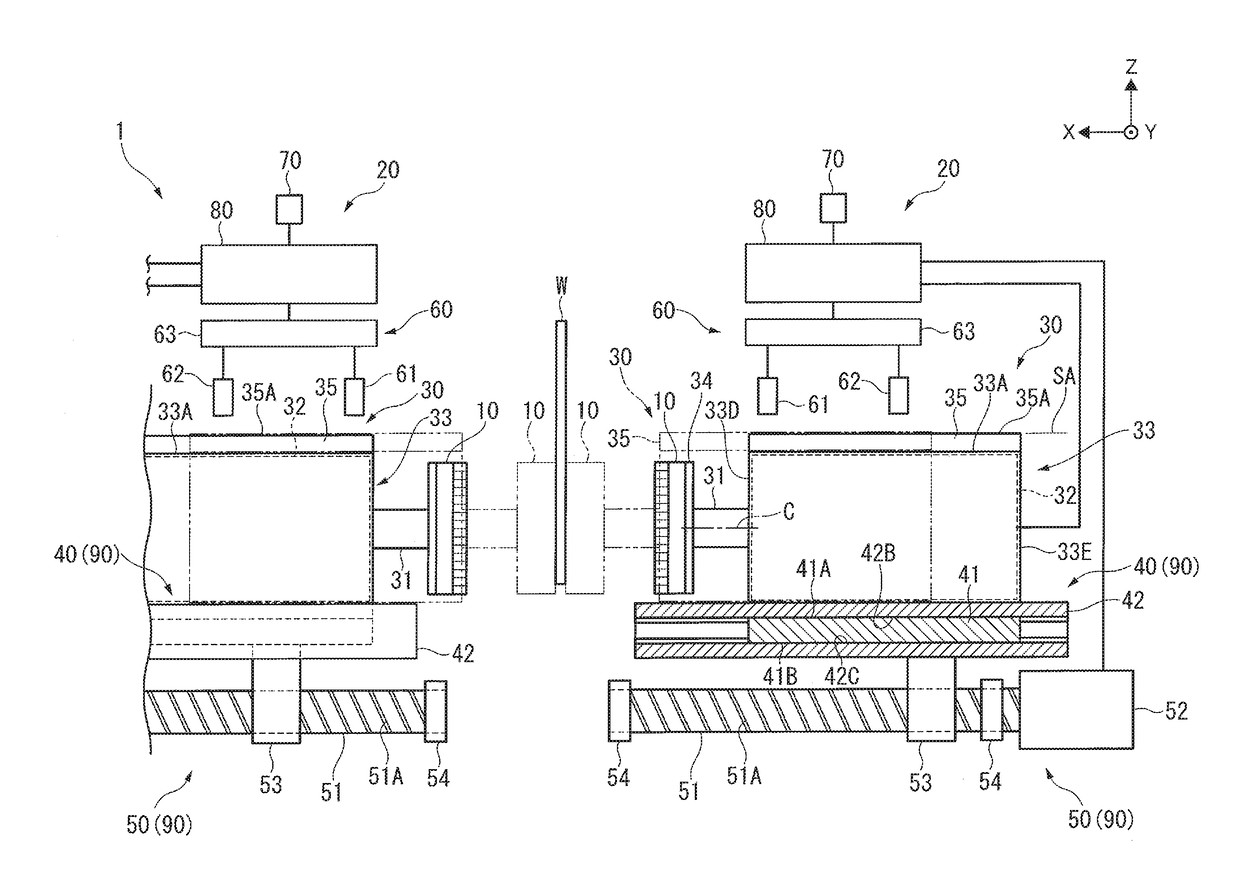
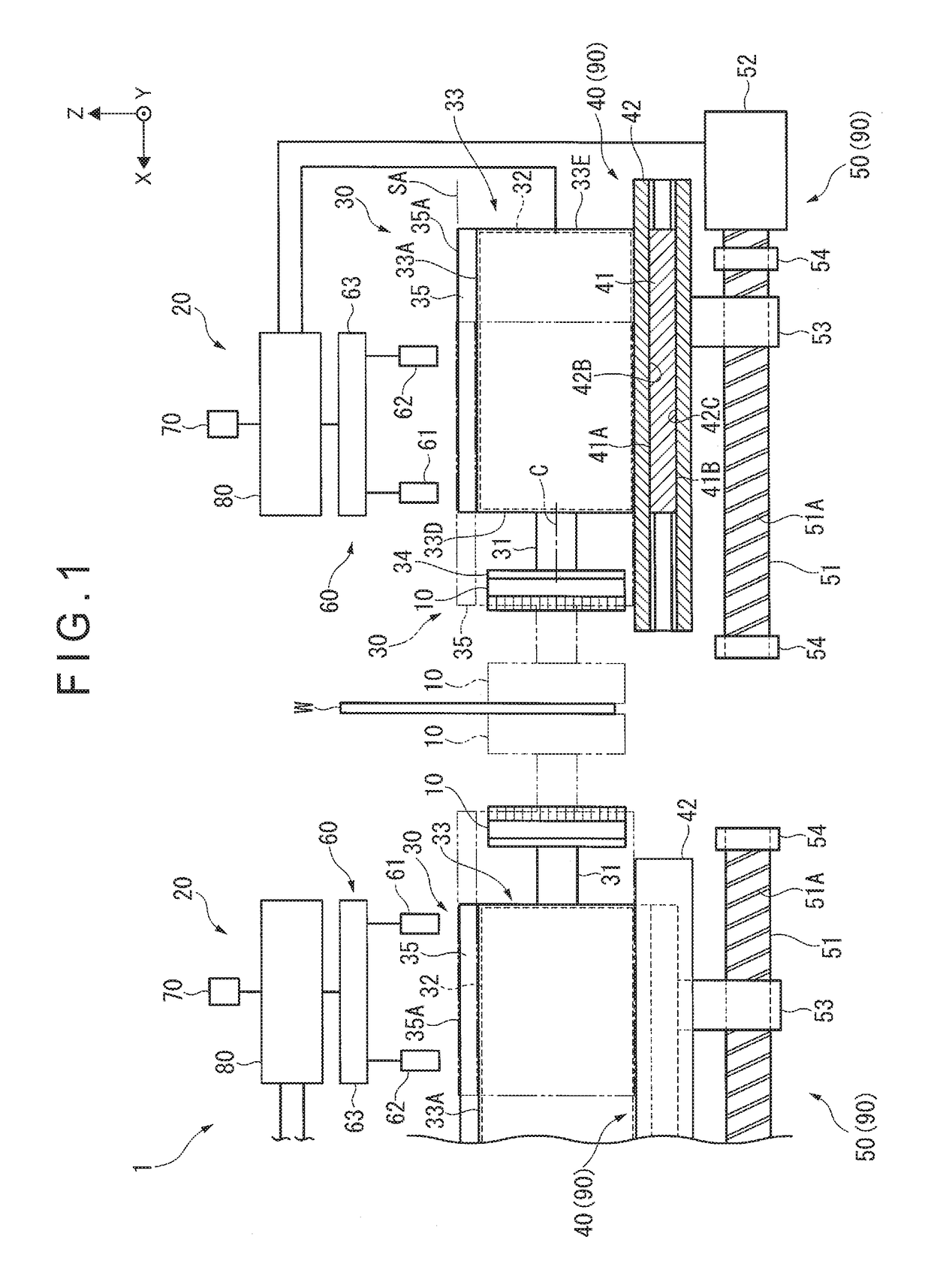
[0033]As shown in FIG. 1, a double-head grinding machine 1 (a grinding machine) grinds a wafer W (an object to be ground) using a grinding wheel 10. The double-head grinding machine 1 includes: a carrier ring (not shown) holding the wafer W therein; a pair of grinding portions 20 disposed on both sides of the wafer W held by the carrier ring; and a grinding liquid supplier (not shown) configured to supply a grinding liquid into the grinding wheel 10.

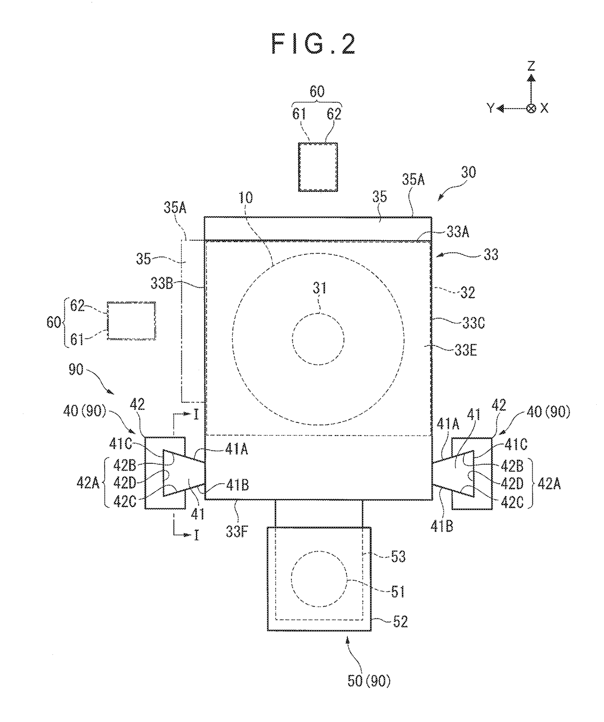
[0034]Each of the grinding portions 20 includes: a spindle driving portion 30; a support 40; an advancement and retraction driver 50; an inclination measuring portion 60; a notifier 70; and a controller 80 as a condition judging portion. The support 40 and the...


PUM


Abstract

A double-head grinding machine includes: a spindle driving portion configured to rotate a spindle to which a grinding wheel is attachable; a moving portion configured to move the spindle driving portions toward and away from a wafer; and an inclination measuring portion configured to measure a change in an inclination of the spindle in association with a movement of the spindle driving portions.

Description

TECHNICAL FIELD[0001]The present invention relates to a grinding machine and a grinding method.BACKGROUND ART[0002]A technology for grinding an object to be ground has been known (see, for instance, Patent Literatures 1 and 2).[0003]Patent Literature 1 discloses a machine for grinding (surface-processing) a semiconductor wafer (object to be ground) (hereinafter, referred to as a wafer).[0004]This machine is configured to support at least one of rotary shafts respectively provided with ring-shaped surface plates to be pressed on both surfaces of the wafer so that the at least one of rotary shafts is tiltable, measure an inclination angle of the at least one of rotary shafts tiltably supported, estimate a shape of the wafer based on the measured inclination angle, compare the estimated result with a target shape, and tilt the at least one of rotary shafts tiltably supported according to the comparison result.[0005]Patent Literature 2 discloses a method for simultaneously grinding both...

Claims


Application Information

Patent Timeline
Patent Type & Authority Applications(United States)
IPC IPC(8): B24B49/00B24B7/17H01L21/304B24B7/22
CPCB24B49/00H01L21/304B24B7/17B24B7/228B24B37/08B24B41/047B24B49/02G01B21/22
Inventor NISHIMURA, YOSHINOBU
Owner SUMCO CORP
Why Eureka
Try Eureka