Flow path member, liquid ejecting apparatus, and production method for flow path member

a technology of flow path and liquid ejector, which is applied in the direction of coating, printing, metal material coating process, etc., can solve the problems of fluid leakage, variable welding failure, and high risk of welding failur

Active Publication Date: 2017-06-08
SEIKO EPSON CORP
View PDF3 Cites 28 Cited by
  • Summary
  • Abstract
  • Description
  • Claims
  • Application Information

AI Technical Summary

Benefits of technology

[0010]One aspect of the invention provides a flow path member in which a plurality of flow path-forming members forms a flow path. The flow path member includes a first flow path-forming member made of a material capable of absorbing a laser light and a second flow path-forming member made of a material that has a lower absorbance with respect to the laser light than the first flow path-forming member and having in a portion of an inner surface that at least partially forms the flow path at least one welded portion that is welded to the first flow path-forming member. An outer surface side of the second flow path-forming member that is an opposite side to the inner surface is provided with at least one light blocking portion capable of blocking the laser light and at least one transmitting portion that is capable of transmitting the laser light and that is positioned on an opposite side to the at least one welded portion. The at least one light blocking portion and the at least one transmitting portion are in contact on at least one boundary with each other. At least one external edge of the at least one welded portion is at a position that is shifted by a shift from the at least one boundary to a side toward which the laser light incident on the at least one boundary at an incident angle less than 90 degrees travels.
[0011]When the second flow path-forming member and the first flow path-forming member are welded by laser light transmitted through the second flow path-forming member, an external edge of a welded portion is formed at a position that the laser light passing through the boundary between a light blocking portion and a transmitting portion reaches. If the incident angle of the laser light on the boundary is 90 degrees, the boundary and the external edge coincide in position when viewed in a direction orthogonal to the outer surface. However, if the incident angle of the laser light on the boundary is less than 90 degrees, the external edge of the welded portion shifts in position from the boundary to the side toward which the laser light travels. In this respect, according to the foregoing construction, since the position of the external edge of the welded portion is set according to the incident angle of the laser light, the first flow path-forming member and the second flow path-forming member are appropriately welded. Therefore, a flow path member in which flow path-forming members are appropriately welded can be provided.
[0012]In the foregoing flow path member, the outer surface of the second flow path-forming member may be provided with a plurality of the at least one boundary that intersects a straight line connecting a first reference position and a second reference position that are apart from each other. Furthermore, each of the at least one external edge of the at least one welded portion may be shifted in position from a corresponding one of the plurality of boundaries by the shift that becomes larger from the first reference position toward the second reference position.
[0013]According to this embodiment, the shifts of the external edges of the welded portions are progressively larger from the first reference position toward the second reference position. Therefore, even if a light source apparatus disposed at a position closer to the first reference position than to the second reference position in a space in contact with the outer surface of the second flow path-forming member emits laser light while pivoting the laser light, appropriate welding is carried out. Hence, the flow path of the flow path member formed by the first flow path-forming member and the second flow path-forming member that are appropriately welded as described above will not have neither an unnecessary fused piece that disturbs fluid flow nor insufficient welding that results in liquid leakage.
[0014]In the foregoing flow path member, the at least one light blocking portion may include an inner-side light blocking portion that corresponds to an inner-side external edge of one of the at least one welded portion which is closer to the first reference position than an outer-side external edge of the one of the at least one welded portion and that is shifted in position so as to be apart from the inner-side external edge and an outer-side light blocking portion that corresponds to the outer-side external edge of the one of the at least one welded portion which is closer to the second reference position than the inner-side external edge of the one of the at least one welded portion and that is shifted in position so as to lie over the outer-side external edge.
[0015]According to this embodiment, a welded portion of the second flow path-forming member is provided so that the position of the inner-side external edge of that welded portion is set by a corresponding inner-side light blocking portion that is shifted in position so as to be apart from the inner-side external edge and the position of the outer-side external edge of the welded portion is set by a corresponding outer-side light blocking portion that is shifted in position so as to lie over the outer-side external edge. Therefore, welding failure is unlikely to occur.

Problems solved by technology

If, in the laser welding as described above, the laser light is not delivered to an appropriate location, various welding failures occur; for instance, a portion that needs to be left unfused is fused and that fused material forms an unnecessary protrusion or a portion that needs to be welded is not sufficiently welded.
Particularly, in the case where the laser welding is performed by scanning laser light by, for example, pivoting a mirror that reflects laser light, if laser light is obliquely incident on the lid member, the irradiated position on the container case shifts from the position of incidence on the lid member, so that a welding failure is likely to occur.
Furthermore, in the case where, in the production of a flow path member, a laser welding failure results from shift of the irradiated position, there is possibility that a fluid may leak from an insufficiently welded site or a fused piece protruded into a flow path may impede flow of a fluid.
Therefore, welding failure is unlikely to occur.

Method used


Image

  • Flow path member, liquid ejecting apparatus, and production method for flow path member
  • Flow path member, liquid ejecting apparatus, and production method for flow path member
  • Flow path member, liquid ejecting apparatus, and production method for flow path member

Examples


Embodiment Construction

[0036]Exemplary embodiments of the liquid ejecting apparatus of the invention will be described in detail hereinafter with reference to the drawings. The liquid ejecting apparatus is, for example, an ink jet type printer that performs recording (printing) by ejecting ink, which is an example of a liquid, to a target such as a sheet of paper.

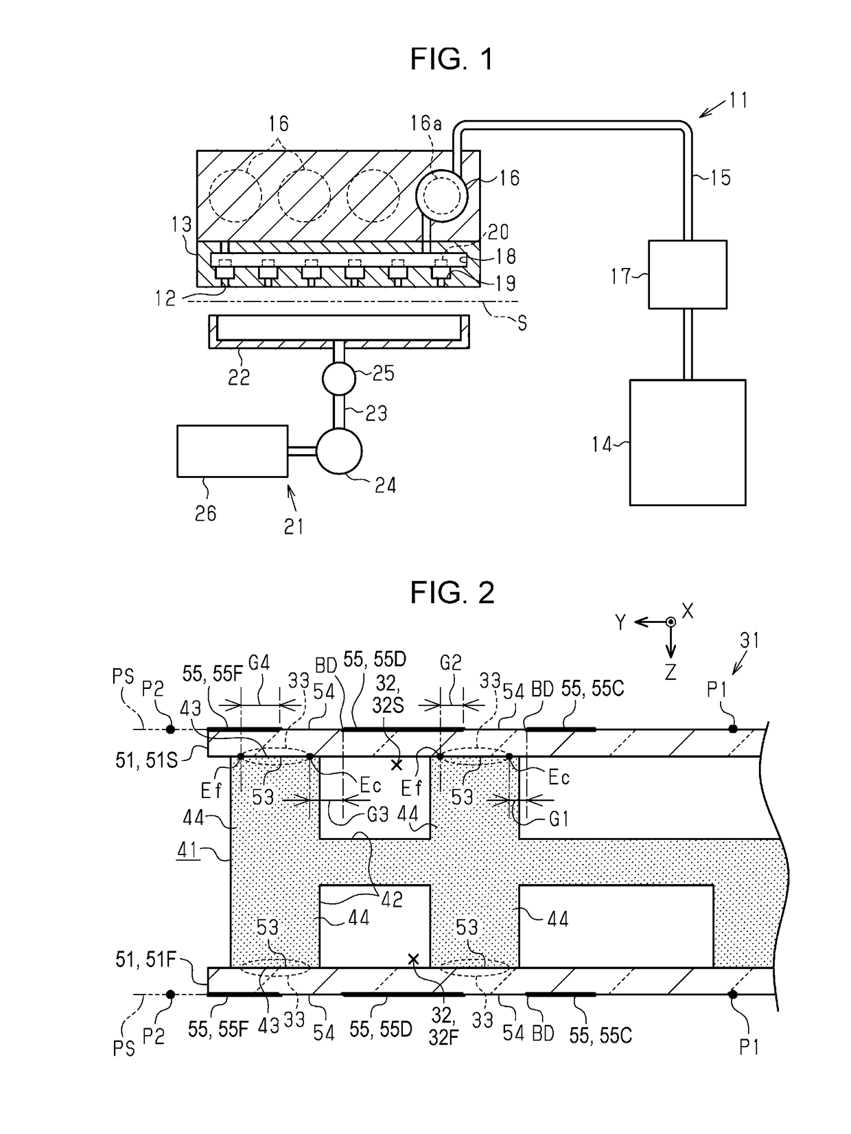
[0037]As shown in FIG. 1, the liquid ejecting apparatus 11 includes a liquid ejecting unit 13 that ejects a liquid from nozzles 12 to a target S, a liquid supply flow path 15 that connects a liquid supply source 14 and the liquid ejecting unit 13, and a pressure regulating mechanism 16 that adjusts the pressure of the liquid supplied to the liquid ejecting unit 13. The liquid ejecting apparatus 11 further includes a pump mechanism 17 that sucks the liquid from the liquid supply source 14 and that discharges the liquid toward the liquid ejecting unit 13 and also includes a maintenance mechanism 21 that performs a maintenance operation for maintain...


PUM

PropertyMeasurementUnit
incident angleaaaaaaaaaa
thickaaaaaaaaaa
heightaaaaaaaaaa

Abstract

A flow path member includes a first flow path-forming member made of a material capable of absorbing a laser light and a second flow path-forming member made of a material that has a lower absorbance with respect to the laser light than the first flow path-forming member and having in a portion of an inner surface that at least partially forms a flow path at least one welded portion that is welded to the first flow path-forming member. An outer surface side of the second flow path-forming member that is an opposite side to the inner surface is provided with at least one light blocking portion capable of blocking the laser light and at least one transmitting portion that is capable of transmitting the laser light and that is positioned on an opposite side to the at least one welded portion and the at least one light blocking portion and the at least one transmitting portion are in contact on at least one boundary with each other. At least one external edge of the at least one welded portion is at a position that is shifted by a shift from the at least one boundary to a side toward which the laser light incident on the at least one boundary at an incident angle less than 90 degrees travels.

Description

BACKGROUND[0001]1. Technical Field[0002]The present invention relates to a flow path member in which a fluid, such as ink, flows, a production method for the flow path member, and a liquid ejecting apparatus, such as an ink jet type printer, which includes the flow path member.[0003]2. Related Art[0004]In some cases in the production of an ink cartridge that is fitted to an ink jet type printer, which is an example of a liquid ejecting apparatus, a container case and a lid member are laser-welded by irradiating the container case made of a laser-absorbing material with the laser light transmitted through the lid member made of a laser-transmitting material (e.g., JP-A-2007-320251).[0005]If, in the laser welding as described above, the laser light is not delivered to an appropriate location, various welding failures occur; for instance, a portion that needs to be left unfused is fused and that fused material forms an unnecessary protrusion or a portion that needs to be welded is not ...

Claims


Application Information

Patent Timeline
Patent Type & Authority Applications(United States)
IPC IPC(8): B41J2/14
CPCB41J2/14145B41J2/01B41J2/175C23C24/10B41J2/14B41J2202/03B41J2002/14306
Inventor YOKOO, AYUMINAKAMURA, HIROYUKI
Owner SEIKO EPSON CORP
Why Eureka
Try Eureka