General purpose engine

a general purpose, versatile technology, applied in the direction of machines/engines, combustion-air/fuel-air treatment, mechanical equipment, etc., can solve the problems of low blowing workability, low blowing workability, high cost, etc., to increase blowing workability and reduce the number of components used

Active Publication Date: 2017-06-08
KAWASAKI MOTORS LTD
View PDF11 Cites 6 Cited by
  • Summary
  • Abstract
  • Description
  • Claims
  • Application Information

AI Technical Summary

Benefits of technology

[0007]In view of the foregoing, the present invention has for its primary object to provide an air cooled general purpose engine having a cleaning access window defined therein, which engine is expected to ha...

Problems solved by technology

When the use of such a working machine for a certain period of time is continued, mowed grasses may often be heaped up as a refuse in gaps between cooling fins around a cylinder and/or a cylinder head, both of which are component parts of the engine, to such an extent as to result in clogging that eventually results in the loss of the cooling function of the engine.
On the other hand, since a filter section, where a cleaner element of the air cleaner is held, is also susceptible to clogging, regula...

Method used


Image

  • General purpose engine
  • General purpose engine
  • General purpose engine

Examples


Embodiment Construction

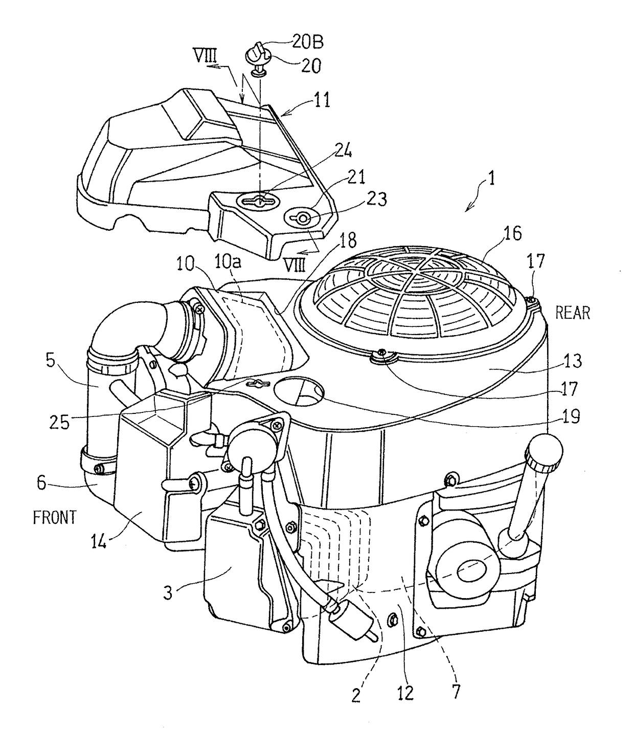
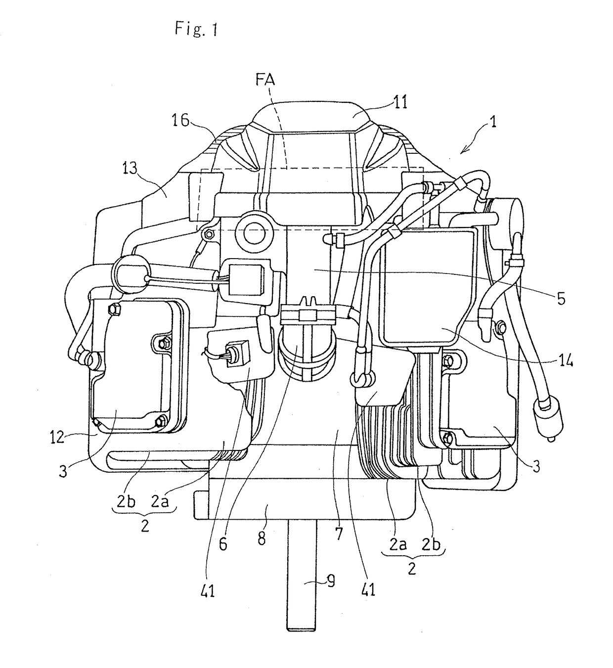
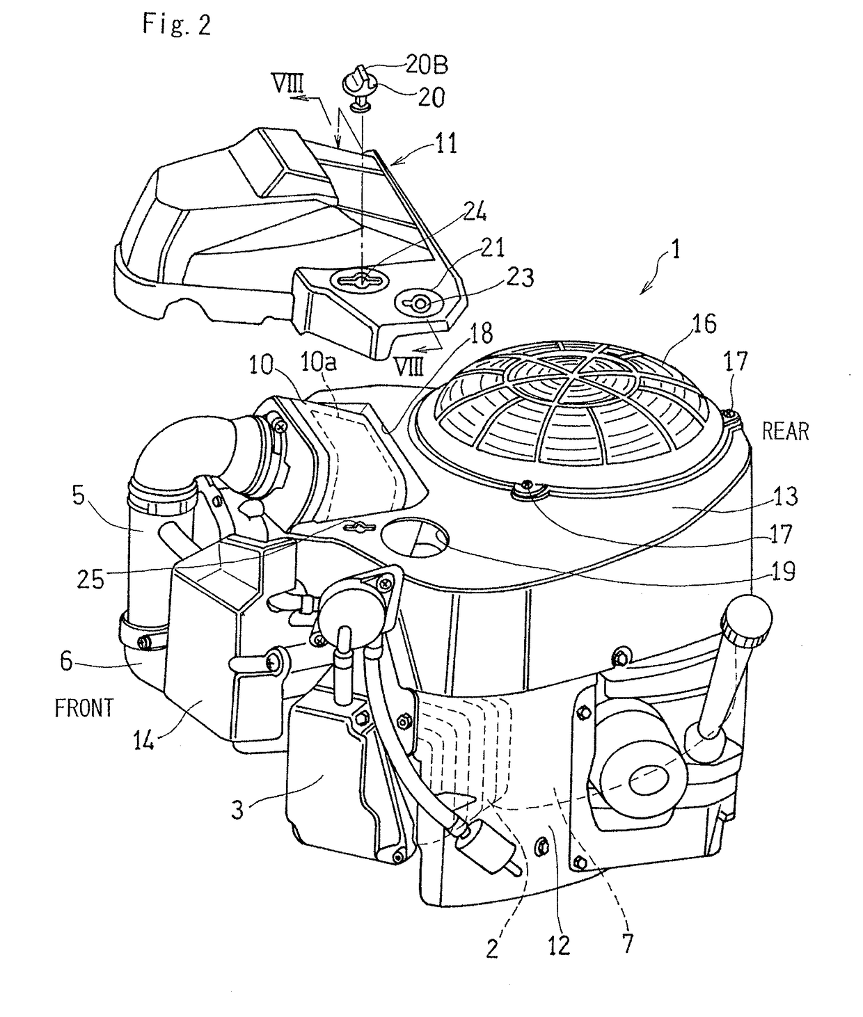
[0030]A preferred embodiment of the present invention will be described in detail with particular reference to the accompanying drawings. In particular, FIG. 1 illustrates a schematic structure of a general purpose engine designed in accordance with the preferred embodiment of the present invention, which engine is shown in a schematic front elevational view. The general purpose engine, generally identified by 1 in FIG. 1, is a compact, air cooled two cycle engine and is used as a drive source for a working machine such as, for example, a lawn mower.

[0031]As FIG. 3 makes it clear, the general purpose engine 1 is a V-shaped two cylinder engine which includes left and right cylinder units 2 and 2, each made up of a cylinder 2a and a cylinder head 2b, which units 2 and 2 are arranged in V-shape. The cylinder units 2 and 2 have respective cylinder axes C and C set at an angle θ which is generally within the range of 70 to 100 degrees, and are set to an angle of 90 degrees relative to ea...


PUM


Abstract

A general purpose engine with a cleaning access window defined therein is in the form of an air cooled engine, having a cylinder unit made up of a cylinder and a cylinder head, and includes a housing for covering at least the cylinder unit and a cleaner covering removably fitted to the housing for covering the filter section of the air cleaner, the housing being formed with a blow window so as to confront gaps between a plurality of cooling fins provided in the cylinder unit, and the cleaner covering has a closing section defined therein for covering the blow window.

Description

BACKGROUND OF THE INVENTION[0001](Field of the Invention)[0002]The present invention relates to a general purpose or versatile engine having a cleaning access window defined therein, which engine is used as a drive source in a working machine such as, for example, a lawn mower.[0003]Description of Related Art[0004]For a drive source in a working machine such as, for example, a lawn mower, a compact air cooled general purpose engine is generally employed. When the use of such a working machine for a certain period of time is continued, mowed grasses may often be heaped up as a refuse in gaps between cooling fins around a cylinder and / or a cylinder head, both of which are component parts of the engine, to such an extent as to result in clogging that eventually results in the loss of the cooling function of the engine.[0005]For this reason, a work to remove the refuse heaped up in the gaps between the cooling fins is regularly or occasionally carried out. On the other hand, since a fil...

Claims


Application Information

Patent Timeline
IPC IPC(8): F02F1/06F02M35/024F02F1/34F02M35/02F01P1/02F01P11/12
CPCF02F1/065F01P1/02F02M35/024F02F1/34F02M35/0201F01P11/12A01D69/002F02B77/00F02M35/04F02B77/04
Inventor COOK, JAKOB DANIELSICS, ALEXANDER ULDIS
Owner KAWASAKI MOTORS LTD
Why Eureka
Try Eureka