Apparatus for thermoelectric recovery of electronic waste heat

a technology of thermoelectric recovery and electronic waste, applied in electrical apparatus, semiconductor devices, semiconductor/solid-state device details, etc., can solve the problems of failure to provide a viable solution, low efficiency, maintenance and energy consumption of a server, etc., and achieve the effect of avoiding overheating of electronic components

Active Publication Date: 2017-06-08
HYPERTECH CIARA INC
View PDF4 Cites 2 Cited by
  • Summary
  • Abstract
  • Description
  • Claims
  • Application Information

AI Technical Summary

Benefits of technology

[0017]According to an embodiment, the one of thermal paste and thermal adhesive has a thermal conductivity substantially smaller than the thermal conductivity of the material of the heat transfer device, the one of thermal paste and thermal adhesive being substantially thinner than the heat transfer device for maintaining, during use, a heat transfer sufficient to avoid overheating of the electronic component.
[0022]According to an embodiment, the heat dissipation device further comprises a pipe for having the heat transfer fluid circulate therein, for improving heat transfer to the heat dissipation device.
[0034]According to an embodiment, the one of thermal paste and thermal adhesive has a thermal conductivity substantially smaller than a thermal conductivity of the heat transfer device, the one of thermal paste and thermal adhesive being substantially thinner than the heat transfer device for maintaining, during use, a heat transfer sufficient to avoid overheating of the electronic component.

Problems solved by technology

The same applies at a smaller scale: the cost for running a server, such as internet servers or data servers found in a data centers, is mainly based on maintenance and energy consumption.
Despite various attempts to convert waste heat from a variety of heat sources using thermoelectric devices, most of them fail to provide a viable solution.
In many heat recovery applications, heat is not sufficiently channeled to the heat generator, resulting in low efficiency.
Applications directed to the conversion of heat waste from electronic devices or electronic components often face a different type of issue.
The thermoelectric generator does not dissipate heat fast enough for the electronic component (e.g. CPU, memory, chipset, etc.), which overheats.
If the electronic component stops working, the heat recovery apparatus becomes useless.

Method used


Image

  • Apparatus for thermoelectric recovery of electronic waste heat
  • Apparatus for thermoelectric recovery of electronic waste heat
  • Apparatus for thermoelectric recovery of electronic waste heat

Examples


Embodiment Construction

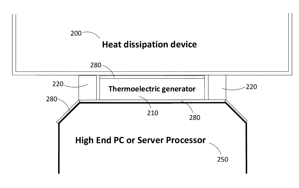
[0055]In embodiments there are disclosed an apparatus and a method for recovering heat (usually waste heat) from an electronic component, such as a processor, a CPU, a physical memory and other components found in a personal computer (PC), in a server or in any other type of computing device which produces heat in a rate sufficient to become an issue.

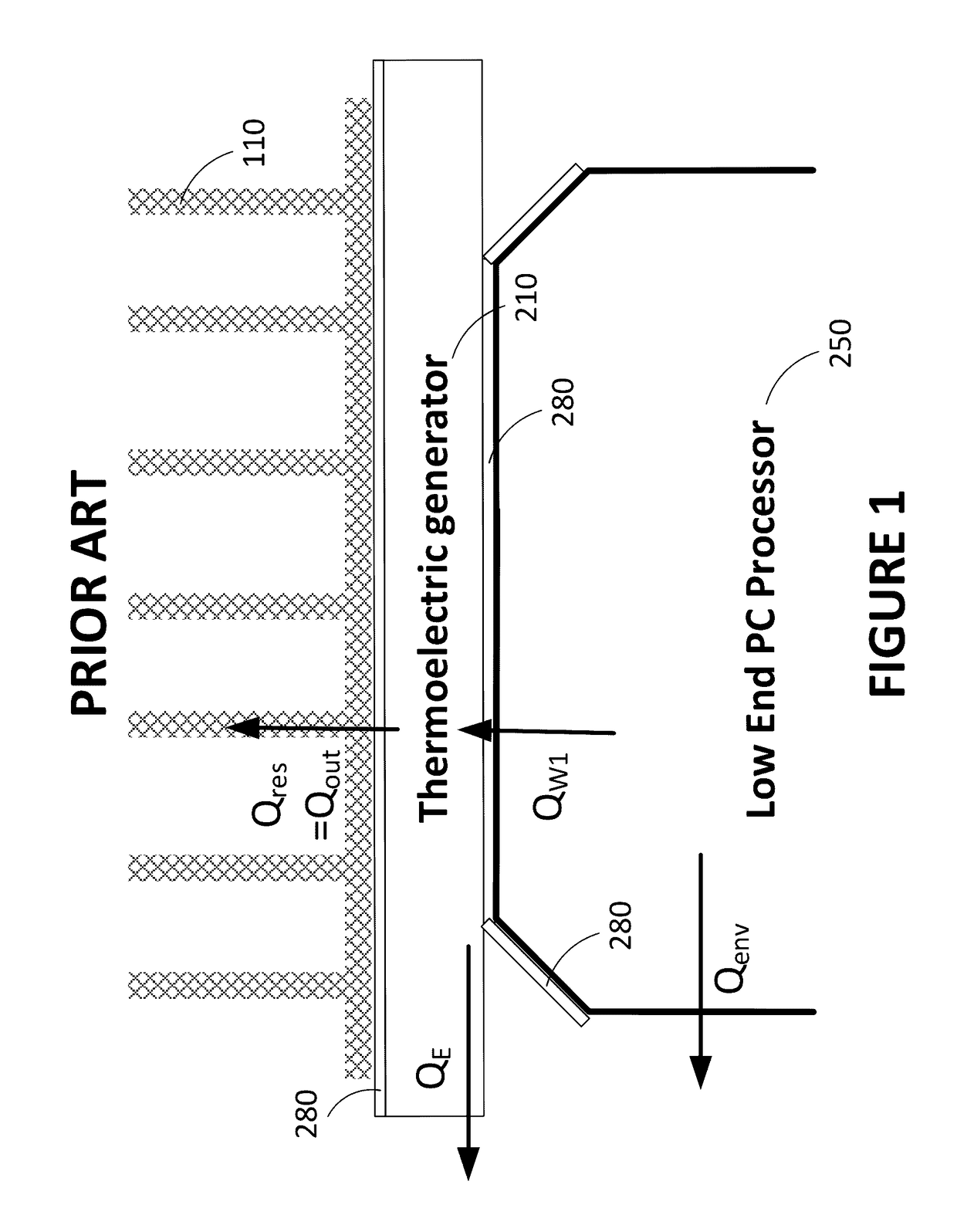
[0056]Referring now to the drawings, and more particularly to FIG. 1, there is shown an embodiment in which there are provided a thermoelectric generator 210 and a radiator or heat sink 110. The waste heat QW generated by the electronic component 250 is dissipated in the thermoelectric generator 210 (QW1) and in the environment (Qenv).

[0057]From the heat entering the thermoelectric generator 210 (QW1), a fraction is transformed into electrical energy via the Seebeck effect (QE). The rest of the heat is residual heat (Qres) that reaches the cold side of the thermoelectric generator 210 to be taken away by the heat sink 110 (Qout=Qres).

[0...


PUM


Abstract

The present document describes an apparatus for recovering heat from an electronic component to generate electric energy. The apparatus comprises a thermoelectric generator having a cold side and a hot side, the hot side being in thermal communication with the electronic component. The apparatus further comprises a heat dissipation device in thermal communication with the cold side of the thermoelectric generator for dissipate heat it receives, and a heat transfer device with a thermal conductivity greater than 200 W(m·K) for directly transferring the heat from the electronic component to the heat dissipation device.

Description

CROSS-REFERENCE TO RELATED APPLICATIONS[0001]This application claims priority from U.S. patent application Ser. No. 14 / 562,210 filed on Dec. 5, 2014.BACKGROUND[0002](a) Field[0003]The subject matter disclosed generally relates to thermoelectric heat conversion. More specifically, it relates to thermoelectric recovery of heat waste from electronic devices.[0004](b) Related Prior Art[0005]It is well known that energy consumption should be reduced where possible, because of environmental considerations, resource rarity and increased prices, among others.[0006]A specific example includes the overall energy consumption of electronic devices, which is increasing on a global level. The same applies at a smaller scale: the cost for running a server, such as internet servers or data servers found in a data centers, is mainly based on maintenance and energy consumption. The predominance of the internet and the increasing popularity of cloud solutions push toward finding solutions to reduce th...

Claims


Application Information

Patent Timeline
Patent Type & Authority Applications(United States)
IPC IPC(8): H01L35/30H01L23/473H01L23/367H01L35/32
CPCH01L35/30H01L23/3672H01L23/473H01L35/32H10N10/17H10N10/13
Inventor AHDOOT, ELIOT
Owner HYPERTECH CIARA INC
Why Eureka
Try Eureka