
Network entry method of millimeter wave communication system and related apparatueses using the same

a technology network entry method, which is applied in the field of network entry method of millimeter wave communication system, can solve the problems of separating an indoor network from an outdoor network, requiring a larger link budget, and poor propagation of electromagnetic waves at higher frequencies

Active Publication Date: 2017-06-08
IND TECH RES INST
View PDF6 Cites 24 Cited by
  • Summary
  • Abstract
  • Description
  • Claims
  • Application Information

AI Technical Summary

Benefits of technology

The patent describes a network entry method and related apparatuses for a millimeter wave communication system. The method involves transmitting Q scan beams with Q identifiers over M mmWave time units, receiving a random access preamble (RAP) in response to the Q scan beams, and determining a best beam or scan beam based on the RAP. The technical effect of this method is to improve network entry and communication efficiency in millimeter wave communication systems.

Problems solved by technology

It has been known that propagation of an electromagnetic wave is typically poorer at higher frequencies than lower frequencies.
On the other hand, additional losses such as the foliage loss which limits the coverage in forests and the heavy rains resulting in several dB losses in a 100 meter link may require larger margin in link budgets according to the high frequency operation.
This would result in isolations of an indoor network from an outdoor network in the mmWave.
For power consumption and cost issues, the transmitter or the receiver may limit the number of RF chains.
However, low data rate due to small BS exists in such the systems.
However, for communication systems that use beamforming for both control signaling and data packets by operating in the mmWave frequency, the current transmission scheme could be inadequate.

Method used


Image

  • Network entry method of millimeter wave communication system and related apparatueses using the same
  • Network entry method of millimeter wave communication system and related apparatueses using the same
  • Network entry method of millimeter wave communication system and related apparatueses using the same

Examples


Embodiment Construction

[0051]Reference will now be made in detail to the present exemplary embodiments of the disclosure, examples of which are illustrated in the accompanying drawings. Wherever possible, the same reference numbers are used in the drawings and the description to refer to the same or like parts.

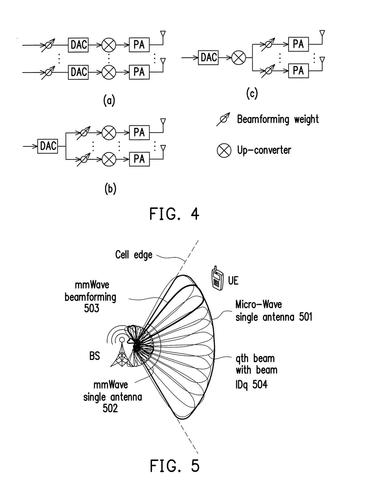
[0052]The disclosure is directed to a network entry method of a millimeter wave communication system and related apparatuses using the same method. The disclosure proposes a time division duplexing (TDD) mmWave frame structure which includes a beamforming (BF) header and a payload (PL) region that follows the BF header. The BF header would include not limited to a downlink (DL) region and an uplink (UL) region. The BF header would provide functions not limited to (BS / UE) beam acquisition, automatic gain control (AGC), timing / frequency synchronization, cell identification, system information (SI) configuration and time advance (TA) for random access (RA). During network entry, the UE beam acquisition...


PUM


Abstract

According to one of the exemplary embodiments, the proposed network entry method is applicable to a user equipment and includes: receiving, within an mmWave band, Q scan beams which have Q IDs over M mmWave time units as each mmWave time unit includes a payload region and a BF header region that includes N BSSs with each of the BSSs corresponding to a different one of the Q scan beams, wherein M, N, and Q are integers greater than 1 and M*N=Q; determining a best beam of the UE based on the BSSs of the Q scan beams; determining a best scan beam of the Q scan beams based on the BSSs of the Q scan beams after determining the best beam of the UE; and transmitting, within the mmWave band, a random access preamble (RAP) by using the best beam of the UE.

Description

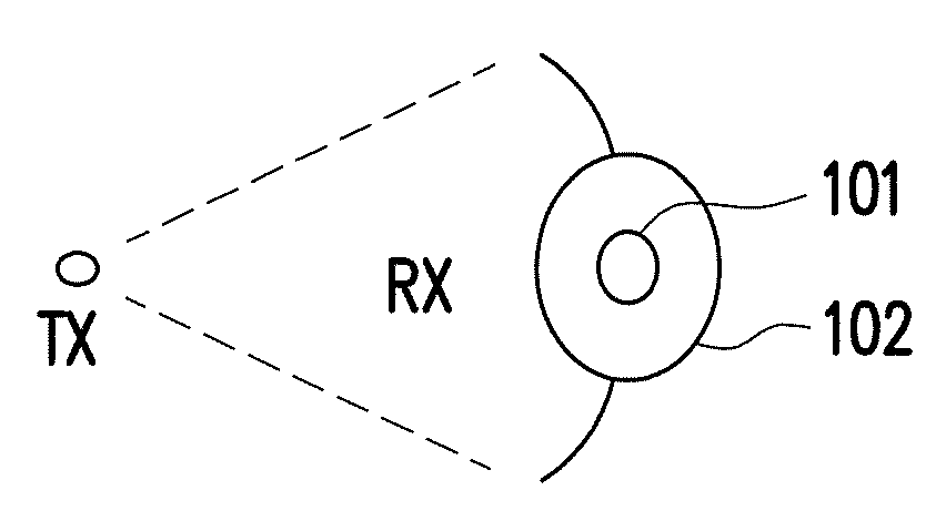
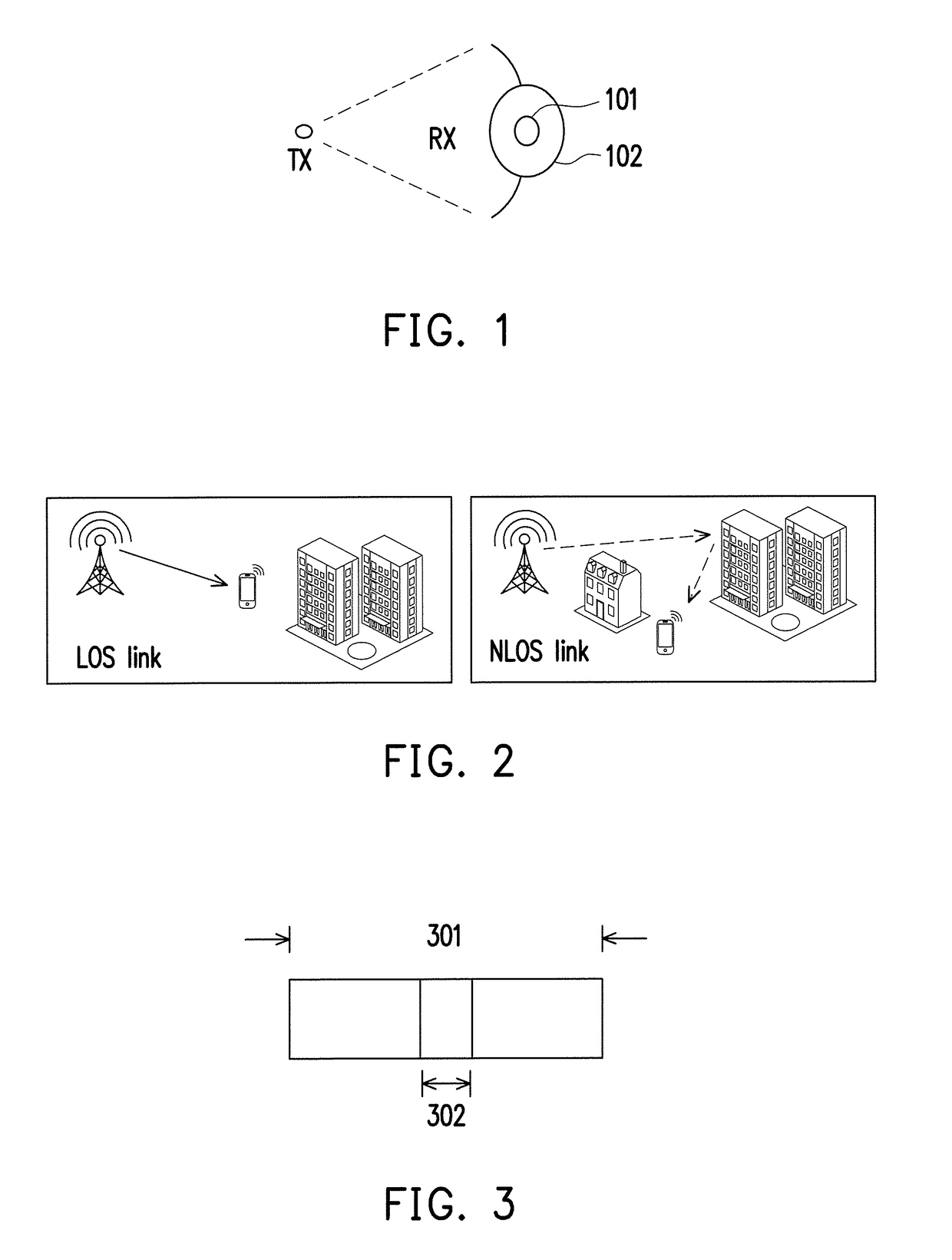
CROSS REFERENCE TO RELATED APPLICATION[0001]This application claims the priority benefit of U.S. provisional application Ser. No. 62 / 262,926 filed on Dec. 4, 2015, and U.S. provisional application Ser. No. 62 / 262,927 filed on Dec. 4, 2015. The entirety of each of the above-mentioned patent applications is hereby incorporated by reference herein and made a part of specification.TECHNICAL FIELD[0002]The disclosure is directed to a network entry method of a millimeter wave communication system and related apparatuses using the same method.BACKGROUND[0003]The antenna array aperture for mmWave is first introduced. It has been known that propagation of an electromagnetic wave is typically poorer at higher frequencies than lower frequencies. For example, the attenuation of electromagnetic waves around the millimeter wave (mmWave) frequency range would typically be higher than the attenuation around the micro wave frequency range as the path loss is usually more severe at higher frequencies...

Claims


Application Information

Patent Timeline
IPC IPC(8): H04W16/28H04W72/04H04L27/26H04W48/16H04W74/08
CPCH04W16/28H04W48/16H04W74/0833H04W88/08H04W72/0446H04W72/0406H04W88/02H04L27/2601H04B7/0695H04B7/088H04L5/0023H04L5/0044H04L5/0048H04L27/2602H04W72/21H04W72/542H04L5/005H04L5/0051H04W36/0088H04W72/046
Inventor HO, CHUNG-LIENCHEN, REN-JRCHEN, WEN-CHIANG
Owner IND TECH RES INST
Learn More