
Emergency Lift and Transport System

a technology of emergency lift and transport system, applied in the field of low-profile stretchers, can solve the problems of corradi failing to lift a patient from the ground, manual lifting the stretcher presents a significant risk of injury, and workers often suffer significant injuries

Active Publication Date: 2017-06-15
KROLICK ROBERT S +2
View PDF3 Cites 5 Cited by
  • Summary
  • Abstract
  • Description
  • Claims
  • Application Information

AI Technical Summary

Benefits of technology

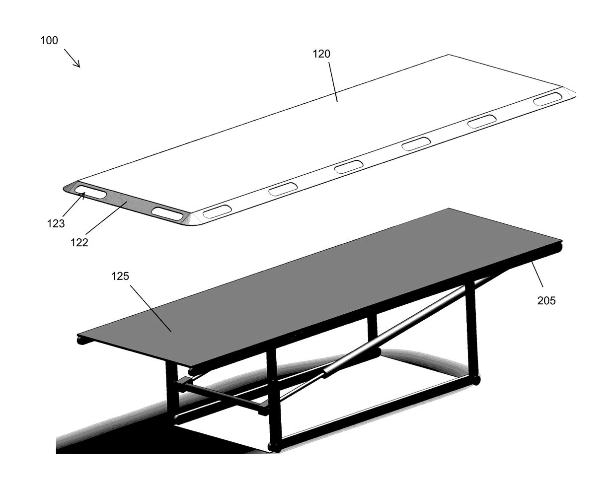
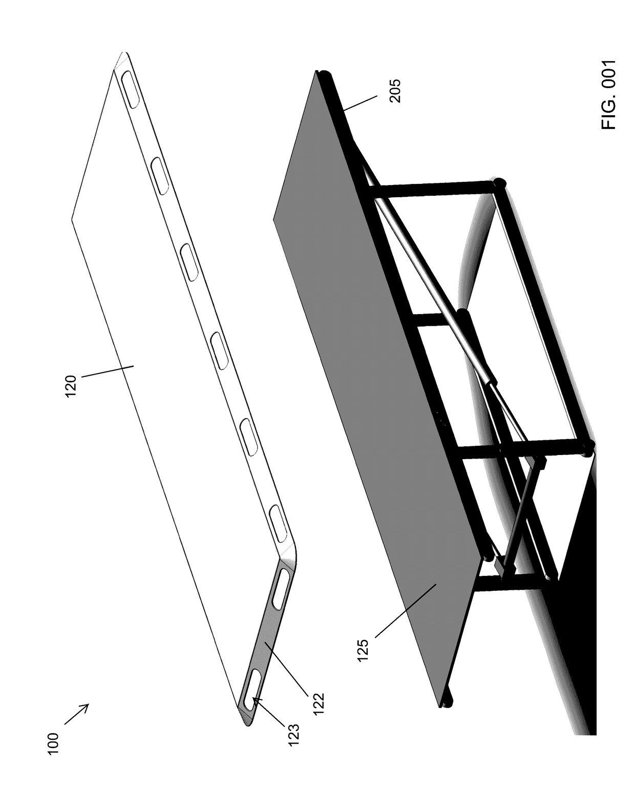
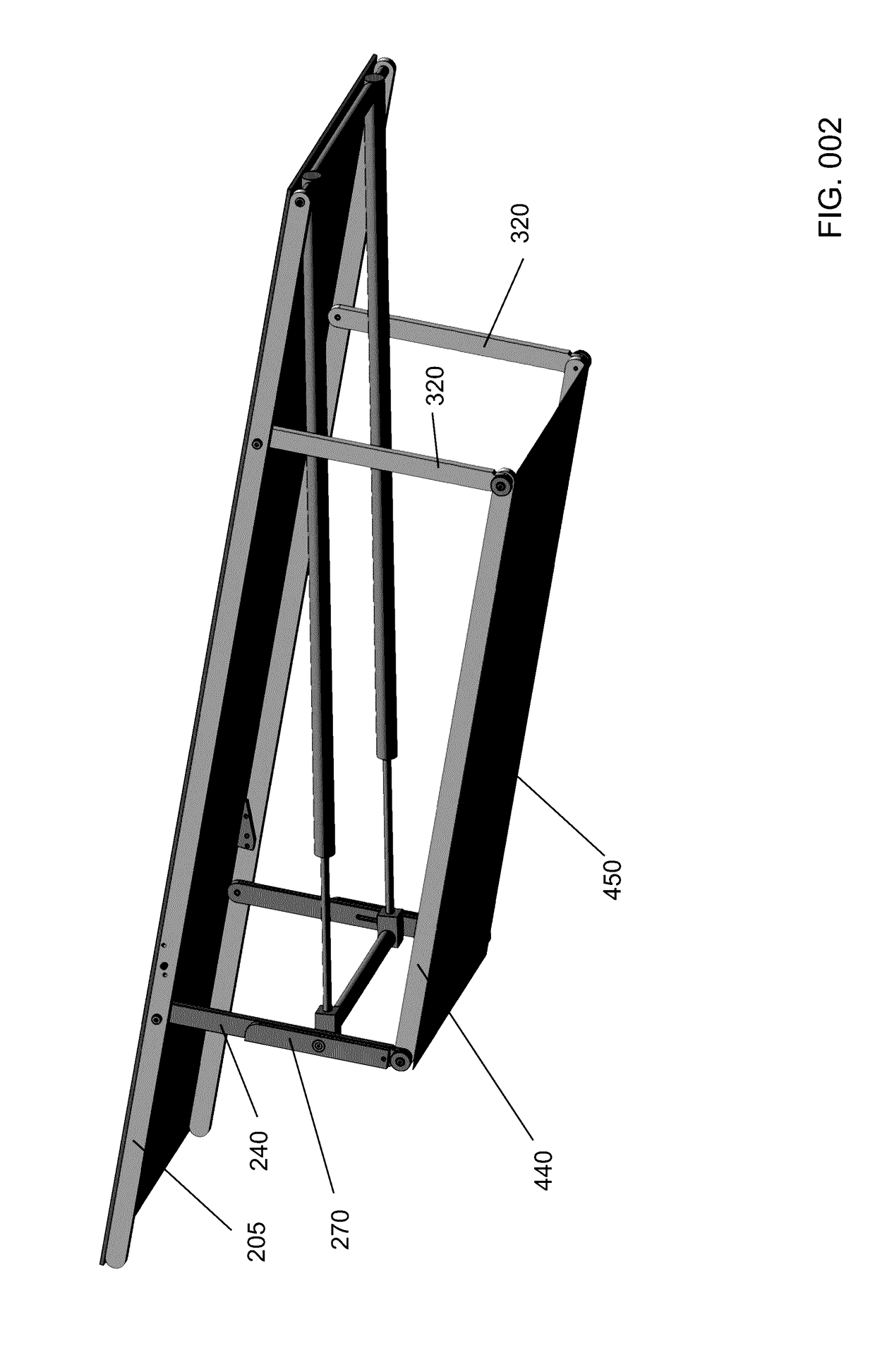
The invention provides a low profile stretcher with mechanical means of lifting a patient in a horizontal position. The unique set of components is layered horizontally to create a compact, easily moved device that reduces the risk of injury to health care workers. The movement of the wheelie bar is assisted by a longitudinal void that retains the powered lower cross bar and helps transfer its movement to the wheelie bar. This creates a smooth and steady transition for the patient during transport.

Problems solved by technology

Such workers often suffer significant injuries in manually lifting a patient off of the ground.
While sliding or rolling a patient upon a low profile prior art cot stretcher presents a minimal risk of injury, manually lifting the stretcher presents a significant risk of injury.
In the related art, stretchers with mechanical means of lift are known, but present a raised profile, inviting injury to workers lifting a patient upon the raised platform.
The Corradi stretcher relies upon a standing frame to keep the structure at a bed level and is not designed to lift a patient from the ground.
While the Corradi stretcher will move a patient from bed to bed, Corradi fails to lift a patient from the ground.
The related art fails to disclose or suggest means or methods of providing a stretcher having a patient surface at near ground level and means of mechanically lifting the patient to a raised position.
Health care workers currently injure themselves lifting up prior art wood and cloth stretchers or from lifting patients upon the raised platforms of prior art mechanical lifts.
Thus, there are significant shortfalls in the art.

Method used


Image

  • Emergency Lift and Transport System
  • Emergency Lift and Transport System
  • Emergency Lift and Transport System

Examples


Embodiment Construction

[0080]The following detailed description is directed to certain specific embodiments of the invention. However, the invention can be embodied in a multitude of different ways as defined and covered by the claims and their equivalents. In this description, reference is made to the drawings wherein like parts are designated with like numerals throughout.

[0081]Unless otherwise noted in this specification or in the claims, all of the terms used in the specification and the claims will have the meanings normally ascribed to these terms by workers in the art.

[0082]Unless the context clearly requires otherwise, throughout the description and the claims, the words “comprise,”“comprising” and the like are to be construed in an inclusive sense as opposed to an exclusive or exhaustive sense; that is to say, in a sense of “including, but not limited to.” Words using the singular or plural number also include the plural or singular number, respectively. Additionally, the words “herein,”“above,”“...


PUM


Abstract

A mechanical lift features the low profile of a traditional wood and cloth cot stretcher allowing patients to be easily rolled or moved upon a flat surface. An integrated mechanical lift system then lifts a patient to a raised position without need for manual lifting. The lift allows patients to be moved and transported without back strain to health care workers or first responders. The lift may be raised by the mechanical movement or expansion of a piston.

Description

RELATED PATENT APPLICATION AND INCORPORATION BY REFERENCE[0001]This utility patent application is a continuation-in-part of U.S. patent application Ser. No. 14 / 741,299 filed on Jun. 16, 2015. This related application is incorporated herein by reference and made a part of this application. If any conflict arises between the disclosure of the invention in this utility application and that in the related provisional application, the disclosure in this utility application shall govern. Moreover, the inventor(s) incorporate herein by reference any and all patents, patent applications, and other documents hard copy or electronic, cited or referred to in this application.BACKGROUND OF THE INVENTION[0002](1) Field of the Invention[0003]The invention generally relates to low profile stretchers that rise in a horizontal position. More particularly, the invention relates to the use of unique rotational and sliding components that are inwardly layered to create a low profile lift that moves a p...

Claims


Application Information

Patent Timeline
Patent Type & Authority Applications(United States)
IPC IPC(8): A61G1/003A61G7/10A61G1/013
CPCA61G1/003A61G7/1013A61G1/013A47C19/045A61G1/0565A61G1/06A61G7/012
Inventor KROLICK, ROBERT S.SHAPIRO, SANFORDCARLING, DUANE
Owner KROLICK ROBERT S
Learn More