Microfluidic device

a microfluidic device and microfluidic chip technology, applied in colloidal chemistry, transportation and packaging, laboratory glassware, etc., can solve the problems of not being able the microfluidic chip device is not intended to generate monodisperse emulsions, and the relative complexity of connecting the microfluidic device with the syringe pump, etc., to achieve the effect of convenient assembly

Active Publication Date: 2017-06-15
NATIONAL TSING HUA UNIVERSITY
View PDF5 Cites 12 Cited by
  • Summary
  • Abstract
  • Description
  • Claims
  • Application Information

AI Technical Summary

Benefits of technology

[0008]Therefore, an object of the disclosure is to provide a microfluidic device with a suction member. With the provision of the suction member, a predetermined suction force (i.e., a negative pressur...

Problems solved by technology

Therefore, it is relatively complicated to connect the microfluidic device with the syring...

Method used


Image

  • Microfluidic device
  • Microfluidic device
  • Microfluidic device

Examples


Embodiment Construction

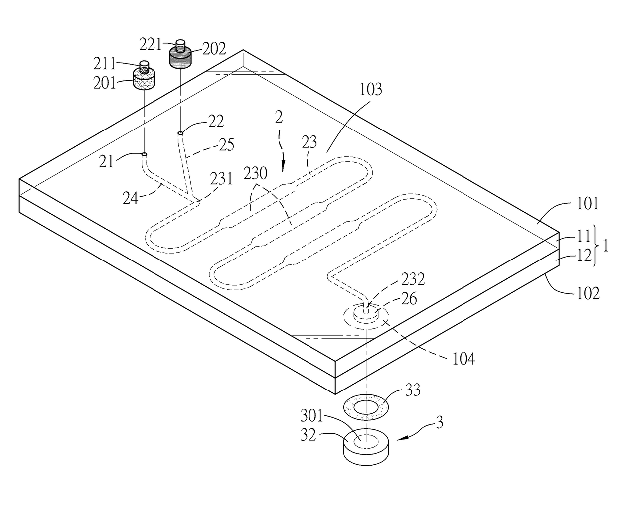
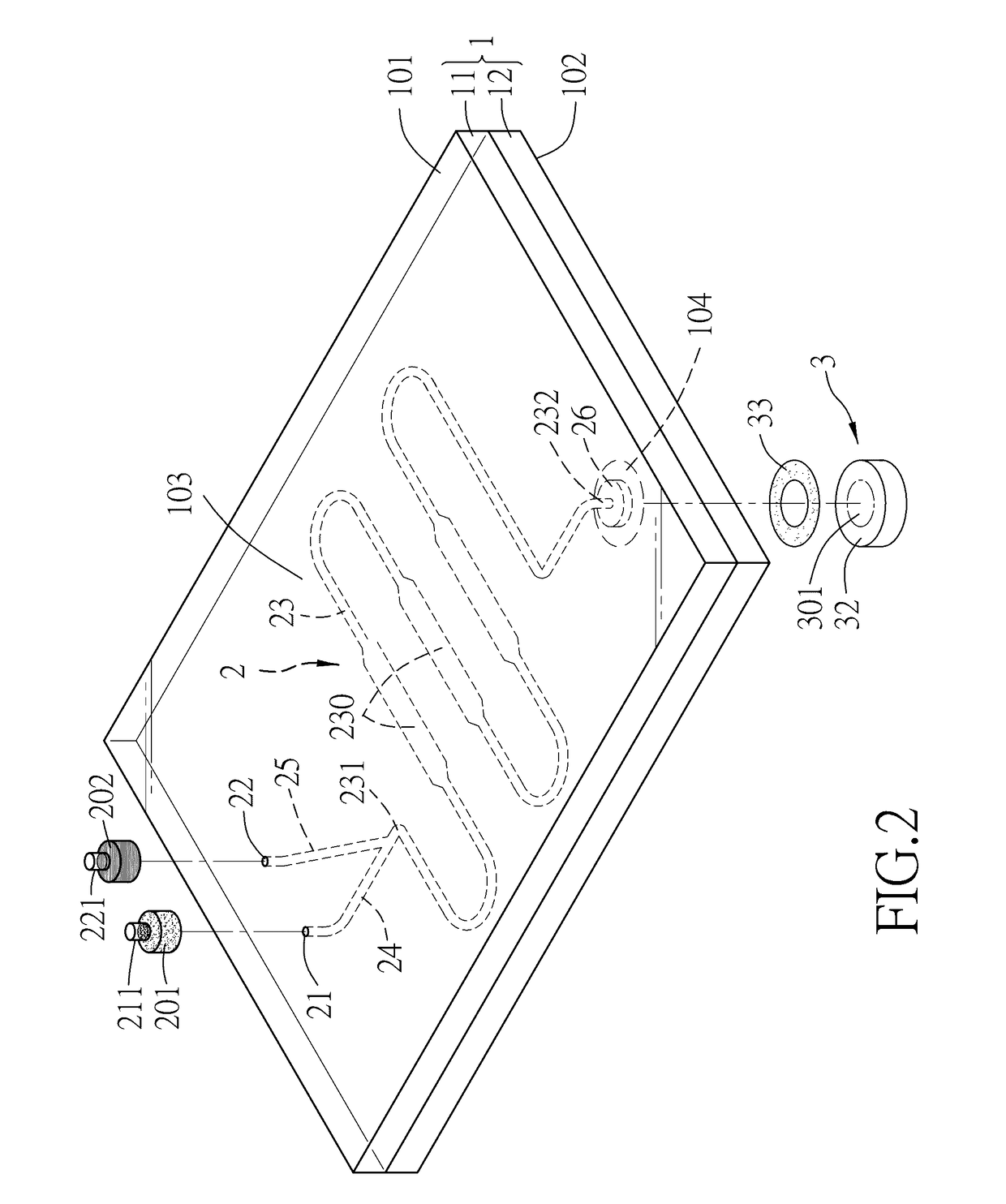
[0018]With reference to FIGS. 2 and 3, a microfluidic device for generating monodisperse emulsions includes a substrate 1, a first capillary inlet 21, a second capillary inlet 22, a microfluidic channel unit 2, an outlet 26, and a suction member 3.

[0019]The substrate 1 has upper and lower surfaces 101, 102, and defines an emulsion forming zone 103 for observation purposes.

[0020]The first capillary inlet 21 is formed in the upper surface 101 of the substrate 1 for passage of a first liquid 201 therethrough.

[0021]The second capillary inlet 22 is formed in the upper surface 101 of the substrate 1 for passage of a second liquid 202 therethrough. The second liquid 202 is immiscible with the first liquid 201.

[0022]The microfluidic channel unit 2 is formed in the substrate 1 and has a high affinity to the first liquid 201. The microfluidic channel unit 2 includes a main channel 23, a first sub-channel 24, and a second sub-channel 25.

[0023]The main channel 23 extends through the emulsion fo...


PUM

PropertyMeasurementUnit
Forceaaaaaaaaaa
Volumeaaaaaaaaaa
Transparencyaaaaaaaaaa

Abstract

A microfluidic device includes a substrate, first and second capillary inlets, a microfluidic channel unit, an outlet disposed downstream of the microfluidic channel unit, and a suction member disposed downstream of the outlet. A first liquid is drawn into a first sub-channel and a main channel of the microfluidic channel unit through the first capillary inlet. A second liquid is drawn into a second sub-channel of the microfluidic channel unit through the second capillary inlet. The suction member provides a predetermined suction force to permit the second liquid to penetrate into the first liquid and to break up into droplets in the first liquid, thereby generating monodisperse emulsions.

Description

CROSS-REFERENCE TO RELATED APPLICATIONS[0001]This application claims priority from Taiwanese application no. 104142028, filed on Dec. 15, 2015.BACKGROUND[0002]Technical Field[0003]The disclosure relates to a microfluidic device, more particularly to a microfluidic device for generating monodisperse emulsions.[0004]Background Information[0005]Conventionally, for generating monodisperse emulsions, a microfluidic device as shown in FIG. 1 may be used. The microfluidic device includes a main channel 90 and two sub-channels 91, 92. An aqueous liquid 901 is delivered to the main channel 90, and an oily liquid 902 is delivered to the two sub-channels 91, 92. Both the aqueous liquid 901 and the oily liquid 902 are driven by a positive pressure supplied by syringe pumps (not shown). Droplets 903 are formed at a place where the aqueous liquid 901 and the oily liquid 902 meet, and are driven by the syringe pumps to an observation zone (not shown) of the microfluidic device for observation. For...

Claims


Application Information

Patent Timeline
IPC IPC(8): B01L3/00B01J13/00
CPCB01L3/502715B01L3/50273B01J13/00B01L2300/0838B01L2300/12B01L2400/049B01L2300/0887B01L2300/161B01L2400/0406B01L2300/0867B01L2300/0883B01L3/0241B01L3/502784B01F23/41B01F25/4331B01F25/4338B01F33/30B01F35/718
Inventor HONG, CHIEN-CHONGLEE, CHIA-HUNG
Owner NATIONAL TSING HUA UNIVERSITY
Why Eureka
Try Eureka