Press forming method and method of manufacturing press formed product

a press forming and press technology, applied in the field of manufacturing, can solve problems such as lack of versatility, and achieve the effects of reducing residual bending moment of formed product, suppressing camber back in formed product, and reducing tensile stress on outer bent side of formed produ

Active Publication Date: 2017-06-15
JFE STEEL CORP
View PDF1 Cites 3 Cited by
  • Summary
  • Abstract
  • Description
  • Claims
  • Application Information

AI Technical Summary

Benefits of technology

[0013]In accordance with the aspect of the present invention, a gap is formed between a head portion of the press die and the blank material. Therefore, in accordance with the aspect of the present invention, during the press forming, the gap between the head portion of the press die and the blank material is crushed in an opposite direction to the bending direction of the blank material, and a compressive stress is generated in the longitudinal direction of the blank material. As a result, in accordance with the aspect of the present invention, a residual tensile stress on an outer bent side of the formed product can be reduced, and a residual bending moment of the formed product can be reduced. Therefore, in accordance with the aspect of the present invention, the occurrence of the camber back in the formed product can be suppressed. In such a way, in accordance with the aspect of the present invention, the camber back that occurs in the formed product can be reduced while reducing the restriction on the shape of the formed product.

Problems solved by technology

However, in the technologies described in Patent Literatures 1 and 2, it is necessary to restrict a shape of the formed product though the camber back that occurs in the formed product can be suppressed, and there has been a problem of lack of versatility.

Method used


Image

  • Press forming method and method of manufacturing press formed product
  • Press forming method and method of manufacturing press formed product
  • Press forming method and method of manufacturing press formed product

Examples


first embodiment

(Camber Back)

[0033]First, prior to a description of a press forming method and a method for manufacturing a press formed product according to a first embodiment, a description is made of a camber back occurrence mechanism in general press forming.

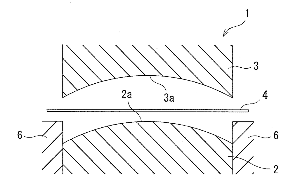
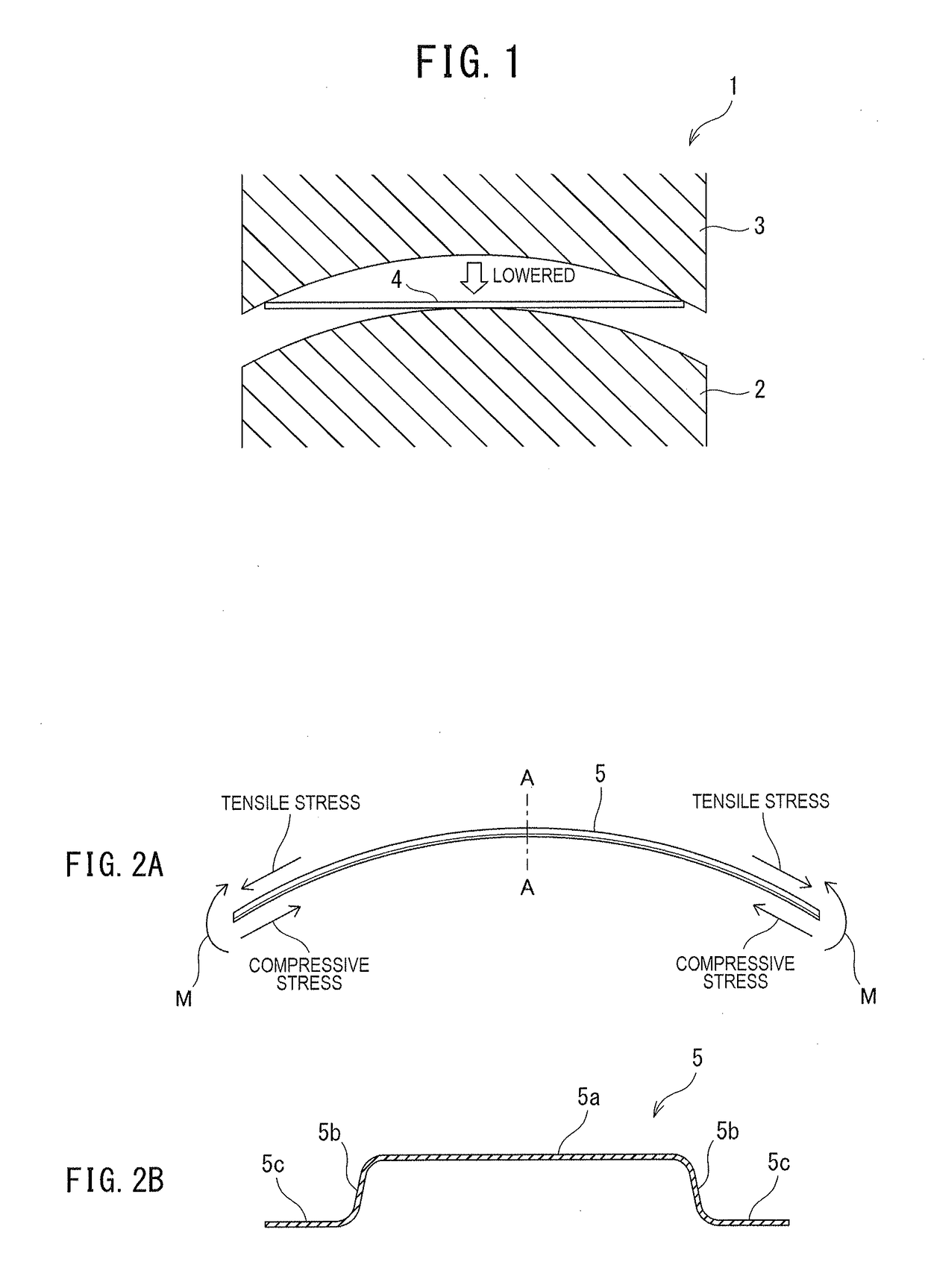
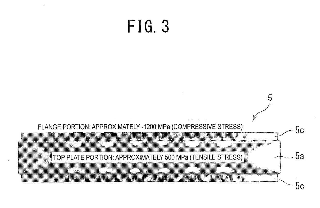
[0034]In usual, as illustrated in FIG. 1 to FIG. 3, when a blank material 4 is manufactured into a press formed product (hereinafter, also referred to as a “hat-shaped member”) 5, which has a hat-shaped cross section and has a bent portion bent to be convex in a direction of a top plate portion 5a, by press forming by using a press forming device 1 (lower die 2, upper die 3), the top plate portion 5a becomes a portion on an outer bent side (convex side), and accordingly, a longitudinal tensile stress is generated in the top plate portion 5a. For example, the blank material 4 is a plate-like raw material cut for the press forming. Moreover, for example, the hat-shaped cross section includes one in which flange portions 5c are further added t...

second embodiment

[0054]Next, a description is made of a second embodiment according to the present invention. Note that the same reference numerals are used for similar constituents and the like to those of the above-described first embodiment, and details thereof are omitted.

[0055]In a press forming method according to the second embodiment, following steps are executed. That is a first forming step of press forming the hat-shaped cross section on the blank material 4, and a second forming step of press forming the bent portion on the blank material 4 on which the hat-shaped cross section is press formed in the first step. Here, in the first forming step, a first press forming device 7 is used. Moreover, in the second forming step, a second press forming device 8 is used.

(Press Forming Device)

[0056]As illustrated in FIG. 9, the first press forming device 7 includes a lower die and an upper die 10 provided above the lower die 9 so as to be capable of ascending / descending. On an upper surface of the ...

modification example

[0069](1) Note that, in the first and second embodiments, the examples of performing the forming as the press forming are illustrated; however, other configurations may be adopted. For example, a configuration of performing draw forming using a wrinkle holder may be adopted.

(2) Moreover, in the first and second embodiments, there are illustrated the examples of forming the hat-shaped member 5, which has such a simple hat-shaped cross section as illustrated in FIGS. 2A and 2B, as the formed product; however, other configurations may be adopted. For example, as illustrated in FIGS. 13A and 13B, there may be adopted a configuration of forming a hat-shaped member 5 having a hat-shaped cross section in which a shape is given to all or apart of the top plate portion 5a.

[0070]Here, FIG. 13A illustrates the hat-shaped member 5 viewed from the side wall portion 5b side, and FIG. 13B illustrates an end surface viewed by cutting the hat-shaped member 5 on a cross section taken along a line B-...


PUM

PropertyMeasurementUnit
tensile stressaaaaaaaaaa
sizeaaaaaaaaaa
friction coefficientaaaaaaaaaa

Abstract

There is provided a press forming method capable of suppressing a camber back, which occurs in a hat-shaped member while reducing a restriction on a shape of the hat-shaped member. At a time of the press forming, a blank material (4) in which a longitudinal line length is at least longer than a longitudinal line length of a top plate portion of a hat-shaped member (5) is fixed between a pair of press dies (lower die (2), upper die (3)), which have bent surfaces (convex surface (2a), concave surface (3a)), while being warped upward, that is, in a bending direction of the lower die (2) and the upper die (3). Subsequently, for the fixed blank material (4), a bent portion of the hat-shaped member (5) is press formed by using the convex surface (2a) and the concave surface (3a).

Description

CROSS-REFERENCE TO RELATED APPLICATIONS[0001]This is the U.S. National Phase application of PCT International Application No. PCT / JP2015 / 000301, filed Jan. 23, 2015, and claims priority to Japanese Patent Application No. 2014-016026, filed Jan. 30, 2014, the disclosures of each of these applications being incorporated herein by reference in their entireties for all purposes.FIELD OF THE INVENTION[0002]The present invention relates to a technology for manufacturing, by press forming, a formed product having a U-shaped cross section having at least a top plate portion and side wall portions continuous with both sides thereof in a width direction, and having a bent portion bent in a plate thickness direction of the top plate portion.BACKGROUND OF THE INVENTION[0003]In recent years, as a structural member of an automobile, a thin high-tensile steel plate or a thin aluminum alloy plate has been more often used in order to reduce weight of a vehicle body. When a formed product is released...

Claims


Application Information

Patent Timeline
Patent Type & Authority Applications(United States)
IPC IPC(8): B21D22/26B21D7/06B21D11/08B21D5/01
CPCB21D22/26B21D11/08B21D7/06B21D5/01B21D53/88B21D22/203B21D22/206B21D35/001
Inventor SHINMIYA, TOYOHISAYAMASAKI, YUJIIIZUKA, EIJI
Owner JFE STEEL CORP
Why Eureka
Try Eureka