
Pressure driven flow crystallizer

a technology of pressure-driven flow and crystallizer, which is applied in the direction of product crystallization, crystallization regulation/control, separation processes, etc., can solve the problems of ever present risk of plugging or clogging

Active Publication Date: 2017-06-15
MASSACHUSETTS INST OF TECH
View PDF1 Cites 4 Cited by
  • Summary
  • Abstract
  • Description
  • Claims
  • Application Information

AI Technical Summary

Benefits of technology

The present invention provides systems and methods for pressure driven flow crystallization. The technical effects of the invention include improved product yield, reduced energy consumption, and improved purity of the product. The methods involve controlling pressure internally of a reaction vessel to remove a given volume of the product when the volume reaches a critical threshold, while not removing the product when the volume is below the threshold. The systems include a reaction vessel with a cavity and a pump for applying pressure periodically or when the volume reaches a critical threshold. The invention also includes a sensor to determine the volume of the product in the vessel and a conduit with a valve to control the pressure in the vessel.

Problems solved by technology

Operations at these scales, where solid-liquid mixtures are required to flow, the risk of plugging or clogging is ever present.

Method used


Image

  • Pressure driven flow crystallizer
  • Pressure driven flow crystallizer
  • Pressure driven flow crystallizer

Examples


example 1

[0057]The following example describes the use of a pressure-driven flow crystallizer, according to some embodiments described herein.

Single-Stage Mixed Suspension, Mixed Product Removal (MSMPR) Crystallizer.

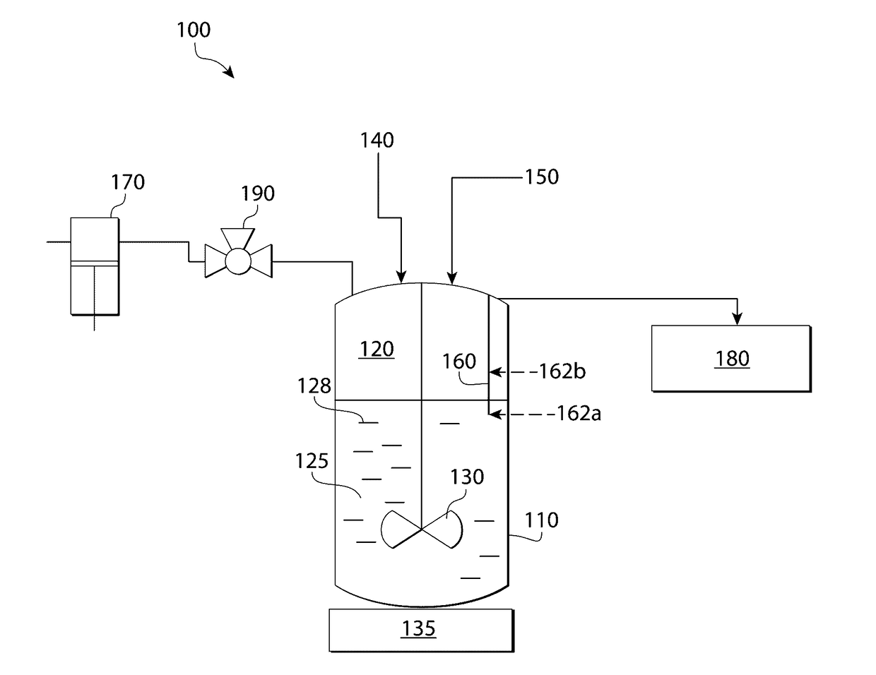
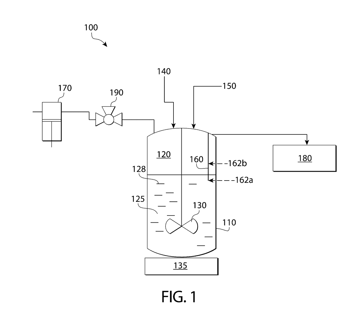
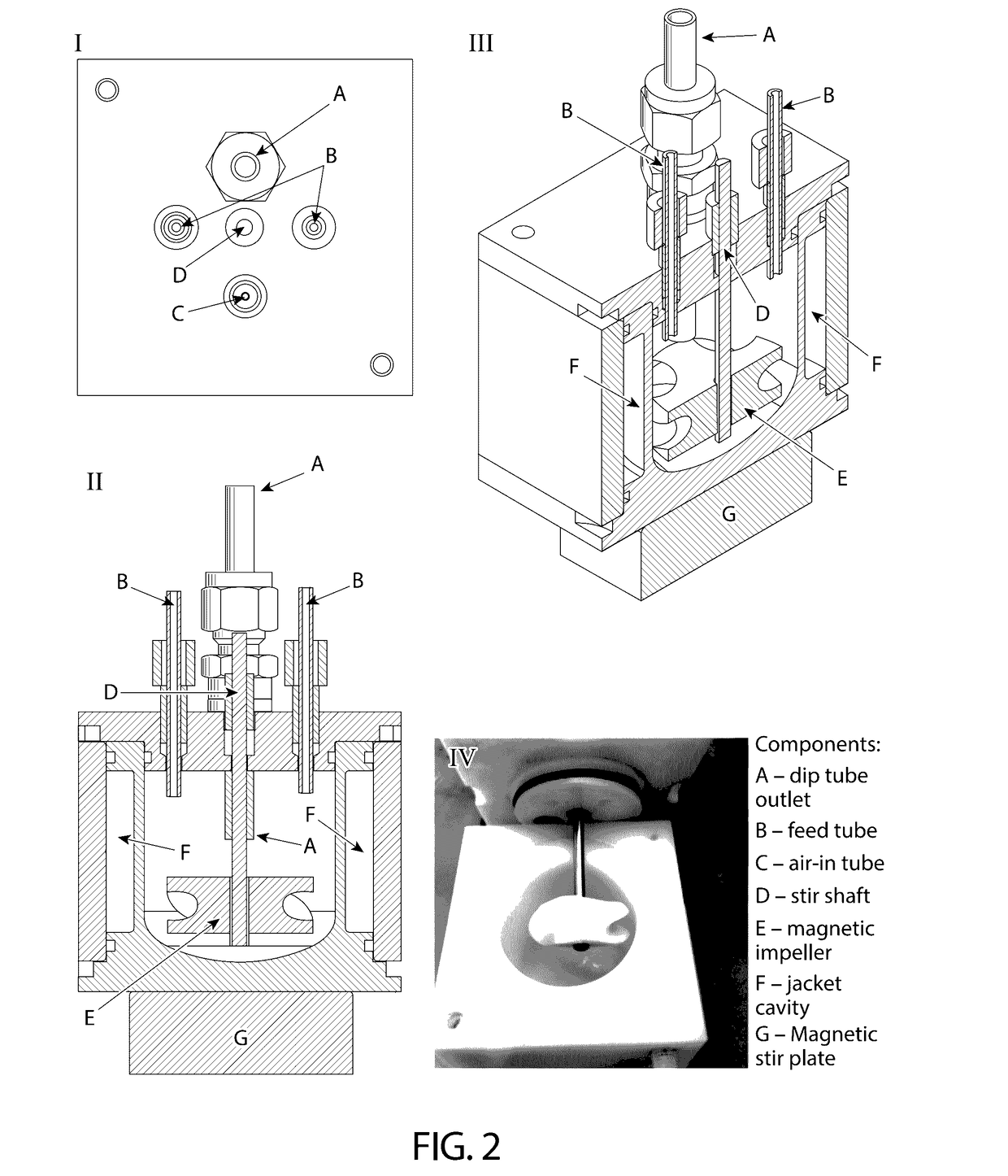
[0058]Feed streams were continuously delivered into the first stage of MSMPR (as shown in FIG. 1) with a diaphragm dosing pump (Model PML-9431-FMM20 manufactured by KNF Flodos AG). The reacting suspension was then transferred out of the MSMPR via a dip tube through the generation of head pressure within the MSMPR vessel. The custom-made crystallizers had a processing scale of between 40 and 200 ml. The feed streams comprised either an API dissolved in solvent which can crystallize in the first stage of the MSMPR due to cooling from the cooling jacket surrounding the crystallizer, or the feed streams consisted of an API solution and an antisolvent stream. The crystallizers used in this study were made of polypropylene and high density polyethylene (HDPE), and had the dimensions of...

example 2

[0067]The follow example demonstrates the use of a pressure-driven flow crystallizer, as described in Example 1.

[0068]The crystallizers had a working volume of 30 mL. For a feed flow rate of 0.01-10 mL / min, possible residence times can range from 3 min to 50 hour for each stage.

Milliliter-Scale Suspension Handling.

[0069]The solubility of azithromycin dihydrate (purchased from Ningbo Samreal Chemical Co. Ltd.) was measured in 60 / 40 vol % acetone (ACS grade, 99.5% purity purchased from Sigma-Aldrich) / water (18.2 mω resistivity) solvent mixture at various temperatures, and at 20° C. at various antisolvent compositions. At each condition, an azithromycin suspension in the appropriate solvent mixture at the desired temperature was stirred for 48 hours. The suspension was then filtered through a 0.2 μm pore size syringe filter and the mother liquor concentration, i.e. solubility at that condition was measured with High Performance Liquid Chromatography (HPLC, Agilent 1200).

[0070]The robu...


PUM

PropertyMeasurementUnit
volumeaaaaaaaaaa
volumeaaaaaaaaaa
volumeaaaaaaaaaa

Abstract

The present invention generally relates to systems and methods for pressure driven flow crystallization. In some embodiments, the system comprises a comprising a cavity and a mixing mechanism. In some embodiments, one or more inlets facilitate the transfer of one or more reagent streams to the cavity. In some such embodiments, the mixing mechanism mixes the first and second reagent streams such that a continuous crystallization and / or generation of a product (e.g., solid particles) in the fluid.

Description

RELATED APPLICATIONS[0001]This application claims priority under 35 U.S.C.§119(e) to co-pending U.S. Provisional Application Ser. No. 62 / 264,843, filed Dec. 8, 2015, which is incorporated herein by reference in its entirety for all purposes.FIELD OF THE INVENTION[0002]The present invention generally relates to systems and methods for pressure driven flow crystallization.BACKGROUND[0003]The pumping and transfer of solids and slurries has generally primarily been of concern only for large scale industrial applications (e.g. liters per min in the transfer of sand and oil slurries in the petrochemical sector or the transfer of coal slurries). These types of slurries are readily handled by centrifugal pumps with large internal clearances.1 Process intensification and continuous flow processing in the pharmaceuticals and fine chemicals industry often requires the use of small scale channels and microreactors (e.g., having a volume on the order of milliliters or microliters) or small conti...

Claims


Application Information

Patent Timeline
Patent Type & Authority Applications(United States)
IPC IPC(8): C07H17/08B01D9/00C07C213/10
CPCC07H17/08C07C213/10C07B2200/13B01D9/0004B01D9/0054B01D9/0036B01D9/0013B01D9/0031B01D9/0059B01D9/0063B01D9/0072B01J8/0025B01F33/4534B01F35/2112B01F35/7543B01F35/92
Inventor MYERSON, ALLAN S.O'MAHONY, MARCUSSTELZER, TORSTENCUI, YUQING
Owner MASSACHUSETTS INST OF TECH
Learn More