Integrated industrial system and control method thereof

a technology of industrial system and control method, applied in computer control, program control, instruments, etc., can solve the problems of loss of the “stronghold for securing safety” role, cyber-attacks may reach the zone of the safety instrumented system, and the integration of industrial system receiving cyber-attacks from outsid

Active Publication Date: 2017-06-15
YOKOGAWA ELECTRIC CORP
View PDF5 Cites 5 Cited by
  • Summary
  • Abstract
  • Description
  • Claims
  • Application Information

AI Technical Summary

Benefits of technology

[0012]An integrated industrial system may include a safety instrumented system which is installed in a first zone, a host system which is connected to the safety instrumented system through a network, the host system being installed in a second zone which is different from the first zone, a detector which is installed in each of the first zone and the second zone, the detector being configured to detect a cyber-attack from outside to a self-zone, and a defender configured to perform a countermeasure of restricting a communication between the first zone and the second zone or of restricting a communication in the first zone or the second zone, based on a detection result of the detector.

Problems solved by technology

There is a possibility that the integrated industrial system receives cyber-attacks from outside.
For this reason, there is a problem that final defense countermeasures depend on security countermeasures applied to the zone where the safety instrumented system belongs.
As a result, since the safety instrumented system is connected to the host system, there is a problem that cyber-attacks may reach the zone where the safety instrumented system belongs.
If such a situation occurs and programs of the controller which is a core of the safety instrumented system are rewritten, a role of “stronghold for securing safety” is lost.

Method used


Image

  • Integrated industrial system and control method thereof
  • Integrated industrial system and control method thereof
  • Integrated industrial system and control method thereof

Examples


first embodiment

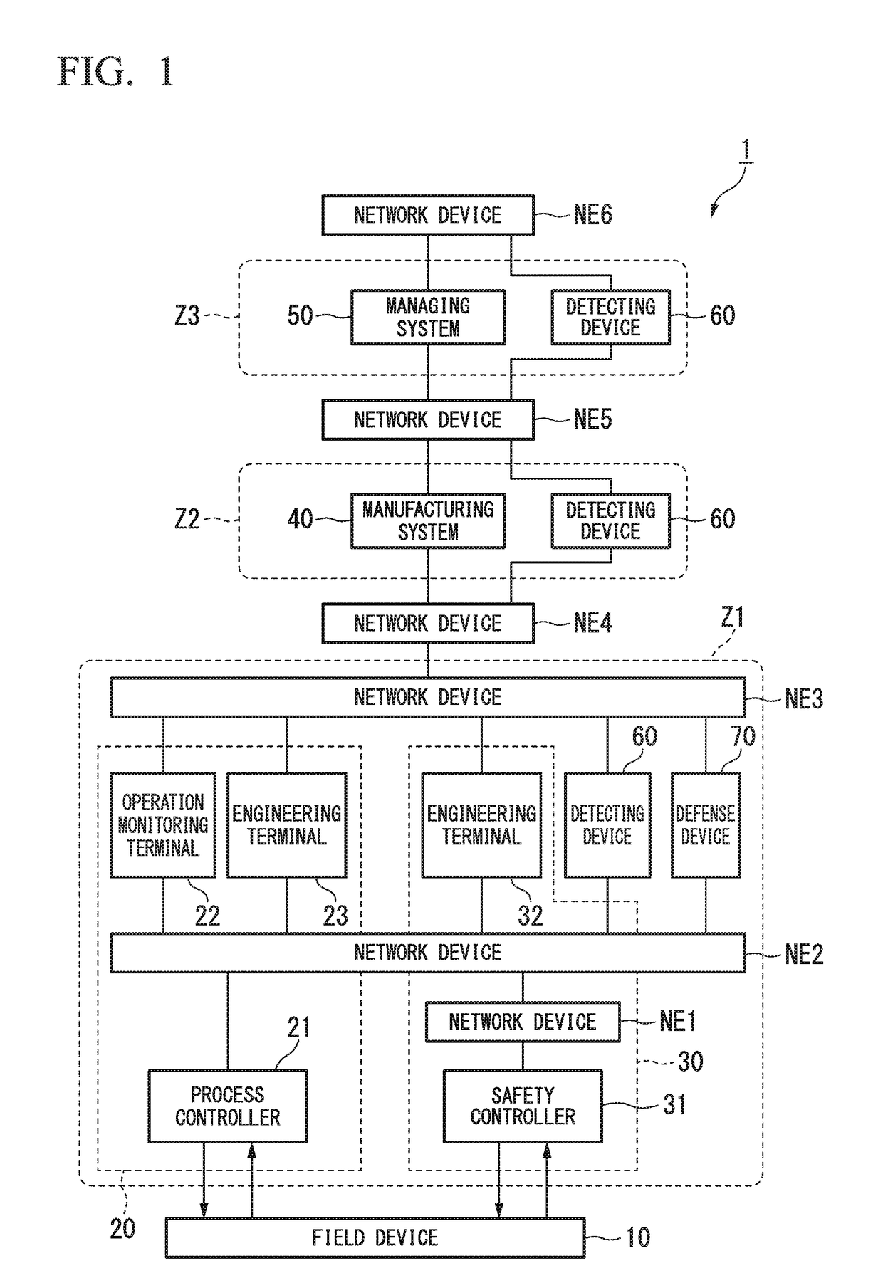
[0030]FIG. 1 is a block diagram illustrating a whole configuration of the integrated industrial system in the first embodiment of the present invention. As shown in FIG. 1, the integrated industrial system 1 of the present embodiment includes a field device 10, a distributed control system (DCS) 20, a safety instrumented system (SIS) 30, a manufacturing system 40 (a host system; a first system), a managing system 50 (a host system; a second system), a detecting device 60 (detector), and a defense device 70 (defender). The integrated industrial system 1 performs automatic operation of a plant, and performs maintenance management of the plant.

[0031]The integrated industrial system 1 is established in conformity with hierarchical structures specified by International Standard ISA-95 (IEC / ISO 62264). Specifically, in the integrated industrial system 1, the distributed control system 20 and the safety instrumented system 30 belong to a hierarchy of level 2, the manufacturing system 40 be...

second embodiment

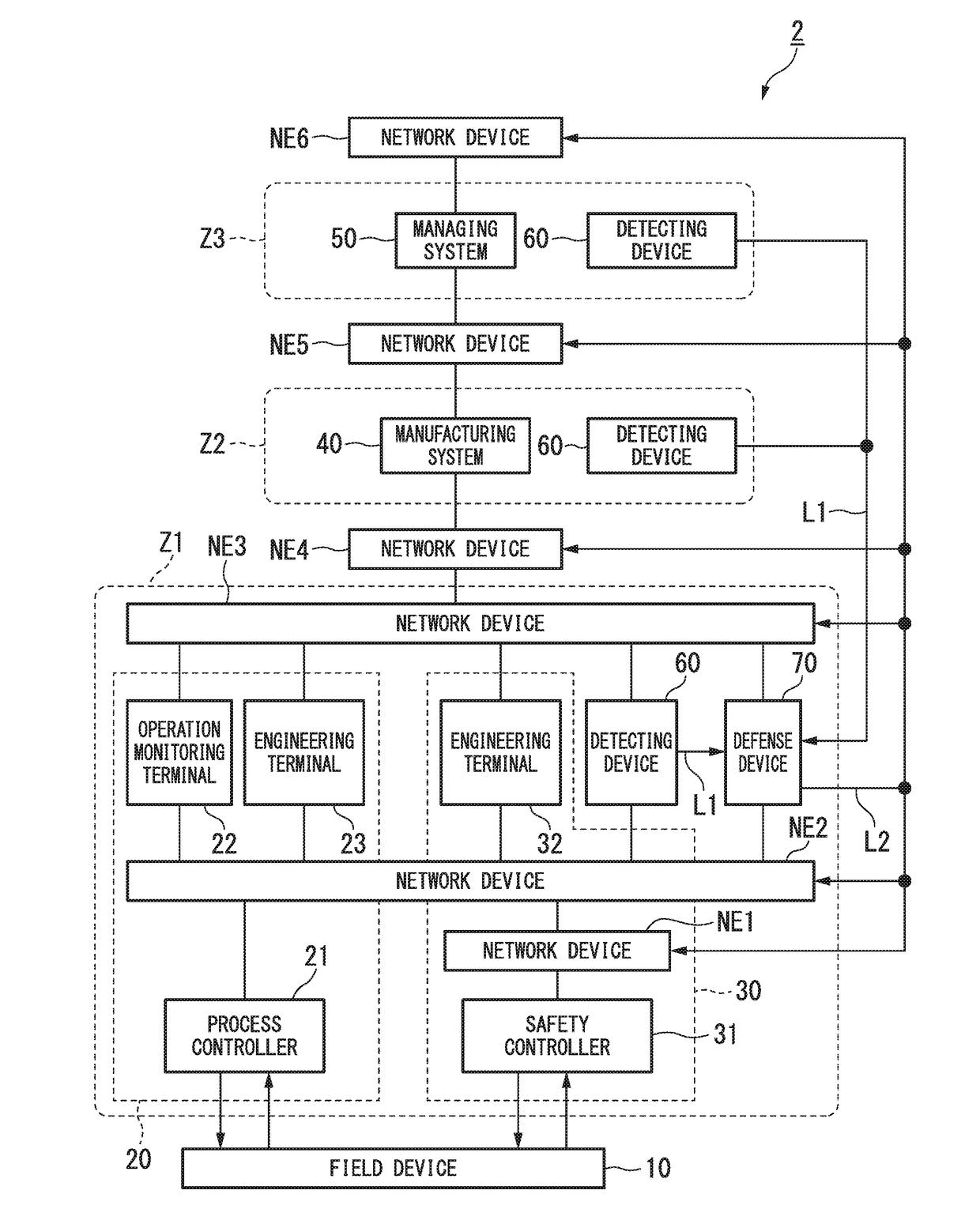
[0066]FIG. 8 is a block diagram illustrating a whole configuration of the integrated industrial system in the second embodiment of the present invention. In FIG. 8, parts that are the same as those in FIG. 1 (or parts that correspond to those in FIG. 1) are assigned the same reference numerals. As shown in FIG. 8, the integrated industrial system 2 of the present embodiment is generally the same configuration as the integrated industrial system 1 shown in FIG. 1. However, the integrated industrial system 2 of the present embodiment is different from the integrated industrial system 1 shown in FIG. 1 in that the detecting device 60 and the defense device 70 are connected to each other through a communication line L1 (first communication line) which is different from the network (the network configured by the network devices NE1 to NE6), and in that the defense device 70 and the network devices NE1 to NE6 are connected through a communication line L2 (second communication line) which ...

third embodiment

[0072]FIG. 9 is a block diagram illustrating a whole configuration of the integrated industrial system in the third embodiment of the present invention. In FIG. 9, parts that are the same as those in FIG. 1 and FIG. 8 (or parts that correspond to those in FIG. 1 and FIG. 8) are assigned the same reference numerals. As shown in FIG. 9, the integrated industrial system 3 of the present embodiment is generally the same configuration as the integrated industrial system 2 shown in FIG. 8. However, the integrated industrial system 3 of the present embodiment is different from the integrated industrial system 2 shown in FIG. 8 in that the defense device 70 is installed in neither of the zones Z1 to Z3 (the defense device 70 belongs to neither of the zones Z1 to Z3).

[0073]If the defense device 70 is installed in the zone Z1 in which the safety instrumented system 30 is installed like the integrated industrial system 2 shown in FIG. 8, the safety instrumented system 30 which plays a role of ...


PUM


Abstract

An integrated industrial system includes a safety instrumented system which is installed in a first zone, a host system which is connected to the safety instrumented system through a network, the host system being installed in a second zone which is different from the first zone, a detector which is installed in each of the first zone and the second zone, the detector being configured to detect a cyber-attack from outside to a self-zone, and a defender configured to perform a countermeasure of restricting a communication between the first zone and the second zone or of restricting a communication in the first zone or the second zone, based on a detection result of the detector.

Description

BACKGROUND[0001]Technical Fields[0002]The disclosure relates to an integrated industrial system and a control method thereof.[0003]Priority is claimed on Japanese Patent Application No. 2015-244221, filed Dec. 15, 2015, the contents of which are incorporated herein by reference.[0004]Related Art[0005]In a plant and a factory (hereinafter, called simply “plant” as a generic name of them), an integrated industrial system is established, and an advanced automatic operation is implemented. In order to secure safety and perform advanced control, the integrated industrial system includes a control system such as a distributed control system (DCS) and a safety system such as a safety instrumented system (SIS). The distributed control system is a process control system which controls industrial process implemented in the plant.[0006]In the distributed control system, field devices (for example, a measurement device and an actuation device) and a controller which controls these field devices...

Claims


Application Information

Patent Timeline
Patent Type & Authority Applications(United States)
IPC IPC(8): H04L29/06G05B19/048
CPCH04L63/1466G05B2219/23317G05B19/048G06F21/554G06F21/561G06F21/57H04L63/02H04L63/14H04L67/12G05B19/0428H04L67/10
Inventor OGAWA, TOSHIKISUZUKI, KAZUYAYAMASHIRO, YASUHIKOFUJITA, SHOHASEGAWA, KENJIKEMMOTSU, TAROKADOWAKI, YUICHIRO
Owner YOKOGAWA ELECTRIC CORP
Why Eureka
Try Eureka