
Using packet filters and network virtualization to restrict network communications

a network communication and packet filter technology, applied in the field of computer system management, can solve the problems of not being able to modify the computing device whose communications are being restricted, and the computing device is restricted in its knowledge of ability to access other devices over the network

Inactive Publication Date: 2006-08-15
MICROSOFT TECH LICENSING LLC
View PDF93 Cites 172 Cited by
  • Summary
  • Abstract
  • Description
  • Claims
  • Application Information

AI Technical Summary

Benefits of technology

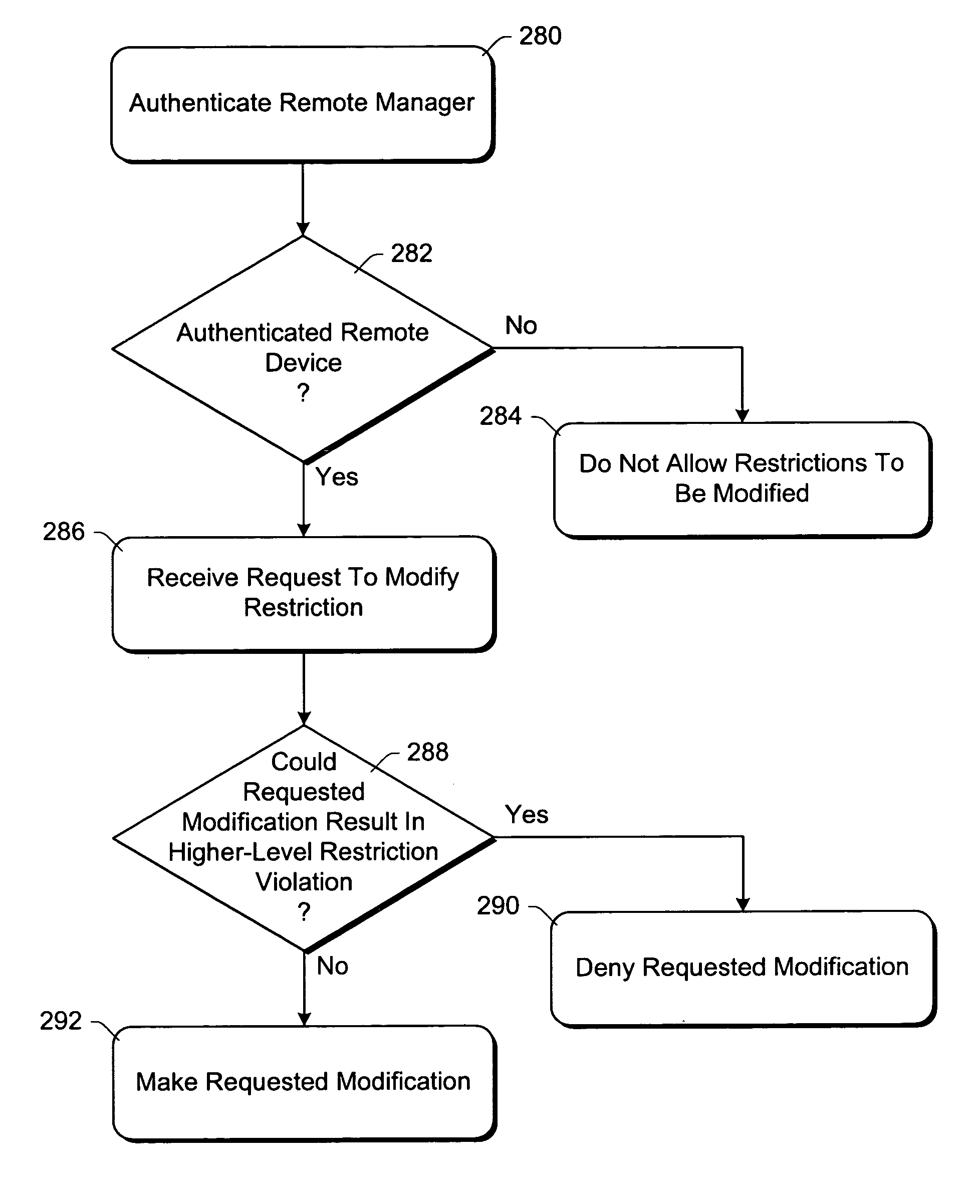
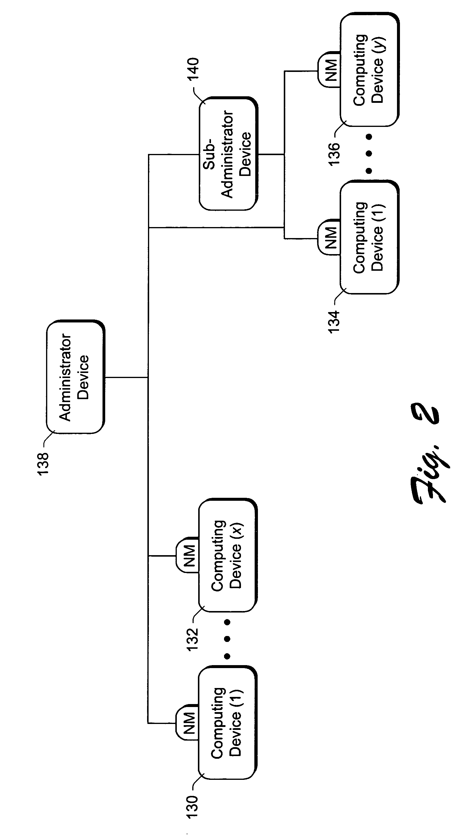
[0010]According to another aspect, a network mediator corresponding to a computing device uses packet filters and a multiple managerial level architecture to restrict network communications. The network mediator includes a set of one or more filters, each filter having parameters that are compared to corresponding parameters of a data packet to be passed through the network mediator (either from or to the computing device). The network mediator then determines whether to allow the data packet through based on whether the data packet parameters match any filter parameters. The set of filters can be modified by remote devices at different managerial levels. However, remote devices are prohibited from modifying filters to make the filters less restrictive than filters imposed by higher level devices.

Problems solved by technology

The set of filters can be modified by a remote device, but cannot be modified by the computing device whose communications are being restricted.
By virtualizing the addresses, the computing device is restricted in its knowledge of and ability to access other devices over the network because it has no knowledge of what the other devices' addresses are.
However, remote devices are prohibited from modifying filters to make the filters less restrictive than filters imposed by higher level devices.

Method used


Image

  • Using packet filters and network virtualization to restrict network communications
  • Using packet filters and network virtualization to restrict network communications
  • Using packet filters and network virtualization to restrict network communications

Examples


Embodiment Construction

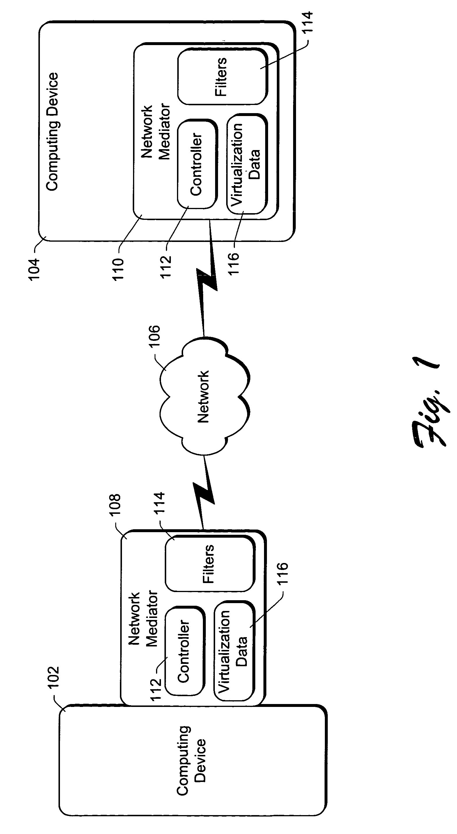
[0020]FIG. 1 shows a network environment such as may be used with certain embodiments of the invention. The network environment in FIG. 1 is illustrated with reference to two computing devices 102 and 104 communicating via a network 106. Only two computing devices are illustrated in FIG. 1 so as not to clutter the drawings. It is to be appreciated that the invention may be used with any number of computing devices coupled together.

[0021]Computing devices 102 and 104 communicate with each other over a data communications network 106. Communications network 106 can be any of a variety of networks, including a public network (e.g., the Internet), as well as a private network (e.g., a corporate local area network (LAN) or wide area network (WAN)), or combinations thereof. Communications network 106 can be implemented in any of a variety of different manners, including wired and / or wireless communications media. Communications network 106 can be of any of a wide variety of complexities, ...


PUM


Abstract

A network mediator corresponding to a computing device uses packet filters to restrict network communications. The network mediator includes a set of one or more filters, each filter having parameters that are compared to corresponding parameters of a data packet to be passed through the network mediator. The network mediator determines whether to allow the data packet through based on whether the data packet parameters match any filter parameters. The set of filters can be modified by a remote device, but cannot be modified by the computing device whose communications are being restricted. When a data packet is sent from the computing device, the data packet will include the virtual address which is changed to the network address by the network mediator prior to forwarding the packet on the network, and vice versa. By virtualizing the addresses, the computing device is restricted in accessing other devices over the network.

Description

TECHNICAL FIELD[0001]This invention relates to computer system management. More particularly, the invention relates to using packet filters and network virtualization to restrict network communications.BACKGROUND OF THE INVENTION[0002]Computers are becoming increasingly interconnected via a wide range of networks, including both public and private networks, such as local area networks (LANs), the Internet, etc. Although such interconnectivity can lead to a number of benefits, so too can it lead to problems. One predominant problem that can arise is that of security, such as how to keep a computer from accessing other computers it should not be accessing, how to keep other computers from accessing your computer, etc.[0003]One specific area in which these security problems can arise is within “co-location facilities”. A co-location facility refers to a complex that can house multiple servers, typically coupled to the Internet. The co-location facility typically provides a reliable Int...

Claims


Application Information

Patent Timeline
Patent Type & Authority Patents(United States)
IPC IPC(8): G06F9/00G06F15/16G06F17/00G06F7/04G06F7/58G06K9/00G06F15/177H04L9/00
CPCH04L63/0263H04L63/0236
Inventor HYDRIE, AAMERHUNT, GALEN C.LEVI, STEVEN P.TABBARA, BASSAMWELLAND, ROBERT V.
Owner MICROSOFT TECH LICENSING LLC
Learn More