
Thermal Isolator Ground Pan For Foundation of Manufactured Building

Active Publication Date: 2010-12-09
OLIVER TECH
View PDF27 Cites 13 Cited by
  • Summary
  • Abstract
  • Description
  • Claims
  • Application Information

AI Technical Summary

Benefits of technology

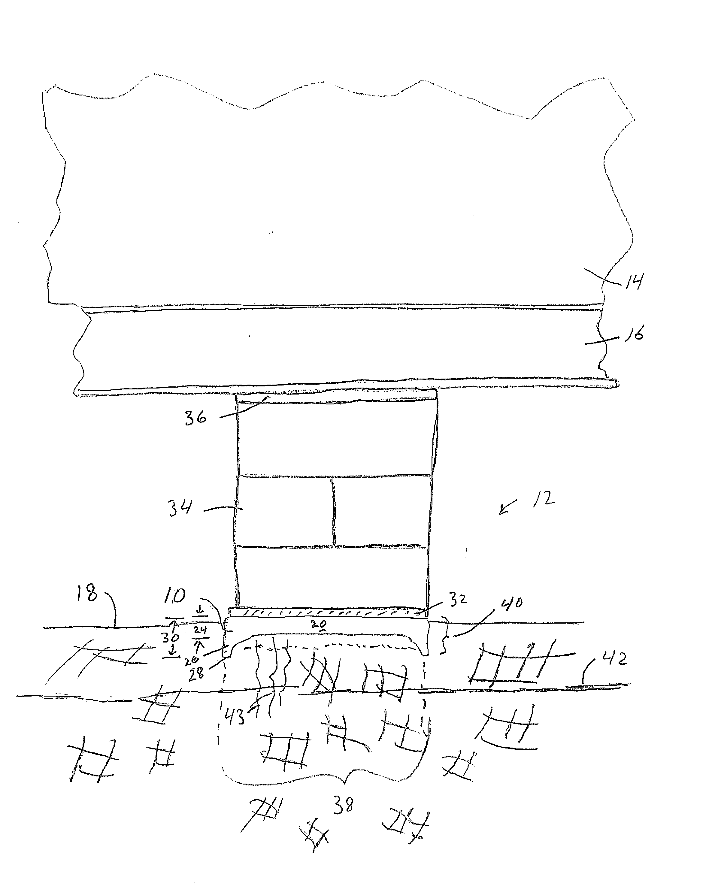
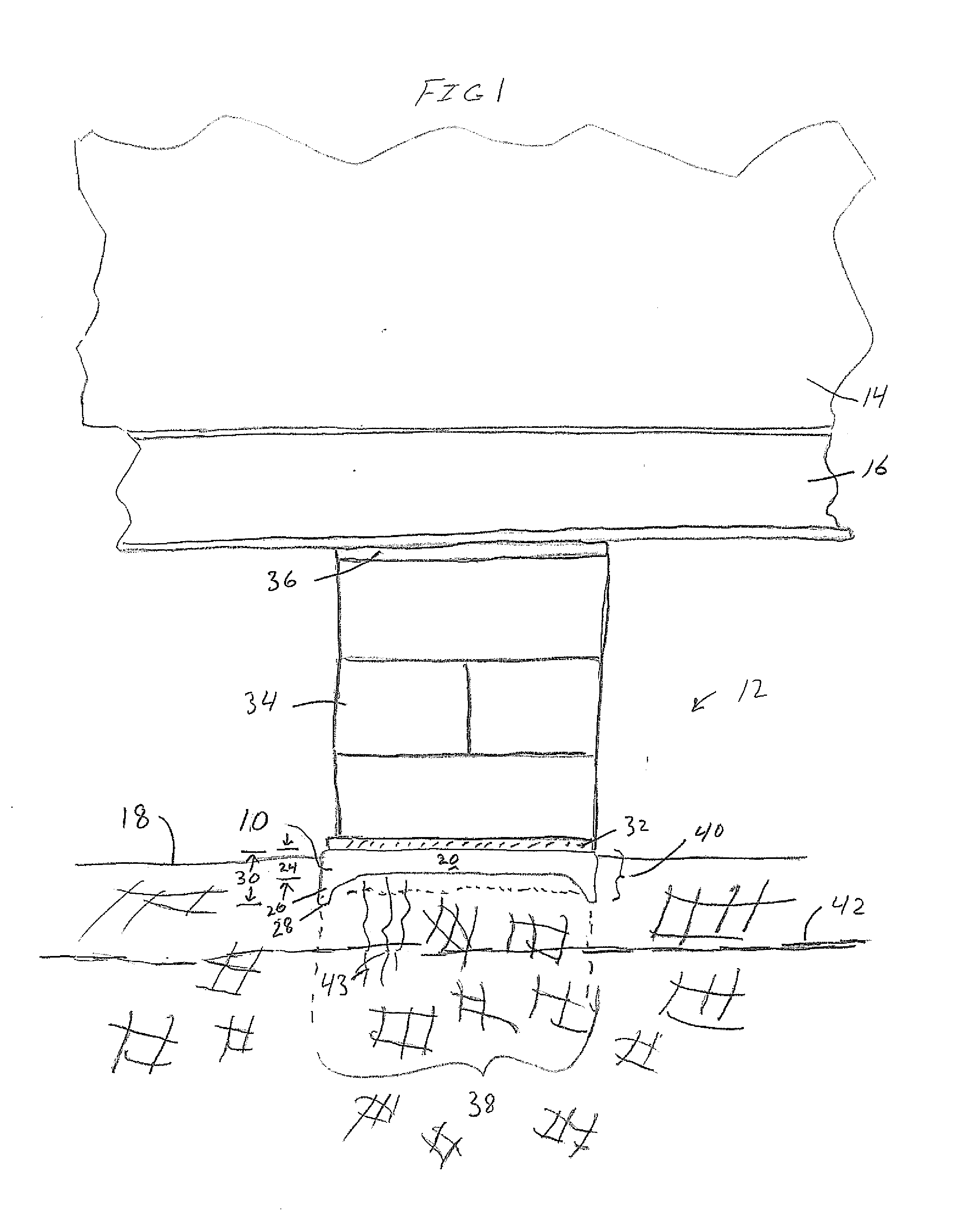
[0007]The present invention meets the need in the art by providing a foundation system for supporting a manufactured building having a support beam, comprising a ground pan having a planar surface received on a ground surface and a thermally insulative cap disposed on the ground pan, whereby the ground pan and thermally insulative cap define in situ a proximate thermally isolated ground column thereunder, with a pier positioned on the ground pan and extending into contact with the support beam for vertically supporting the support beam and transferring the mass of the manufactured home to the ground pan, whereby the thermally insulative cap restricts communication of heat from the proximate thermally isolated ground column for resisting frost heave.

Problems solved by technology

While these foundation assemblies have been successful in resisting wind loads on installed manufactured buildings, there are drawbacks to usage of these foundations in regions of the country in which the ground experiences frost heave.
A building that is not level can result in openings in the building becoming out of skew.
This causes doors to become skewed and not open or close properly such as in doorways and cabinetry.
Windows likewise become difficult to open and close.
Skirting used on the perimeter of manufactured buildings placed at sites with pier supports is not entirely successful in reducing or eliminating frost heave.
Even with skirting, manufactured buildings placed at sites with pier supports and not engineered foundations, are susceptible to frost heave of the ground below the ground pan.

Method used


Image

  • Thermal Isolator Ground Pan For Foundation of Manufactured Building
  • Thermal Isolator Ground Pan For Foundation of Manufactured Building
  • Thermal Isolator Ground Pan For Foundation of Manufactured Building

Examples


Embodiment Construction

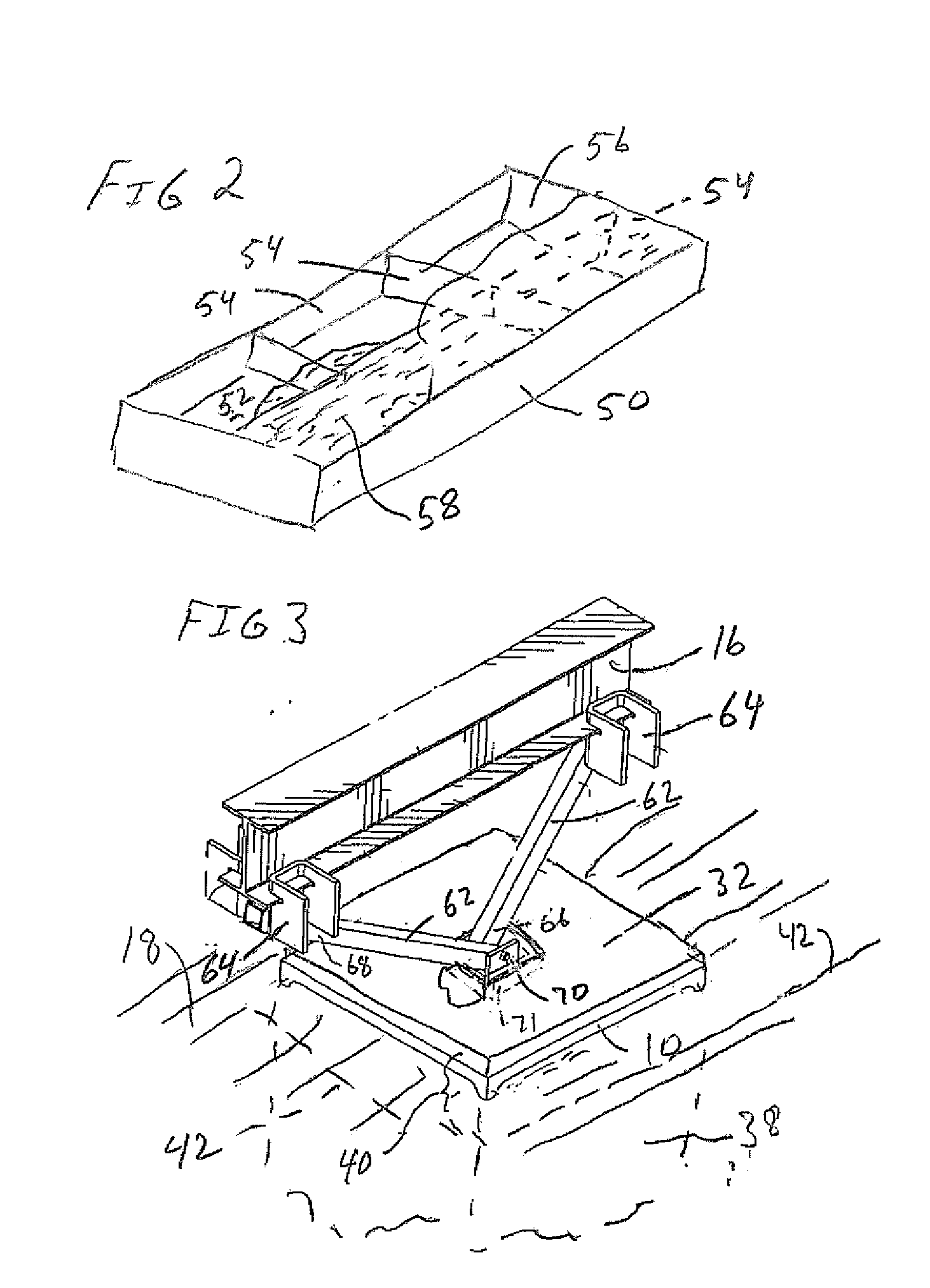
[0020]With reference to the drawings, in which like elements have like identifiers, the present invention provides a thermal isolator ground pan 10 for use with a foundation generally 12 of a manufactured buildings 14. Manufactured buildings have at least one longitudinally extended support beam 16, and typically two, or more, such support beams. The ground pan 10 seats on the ground generally 18. The ground pan 10 interacts with the ground 18 for resisting movement. Typically, this is accomplished by providing ground blades 20 that extend in a first direction substantially perpendicularly from a top surface of the ground pan. For example, opposing side edges of the ground pan 10 fold over to define a pair of opposing ground blades 20 that extend a first distance 24 from the top surface. In the illustrated embodiment, the ground pan 10 is formed from a metal sheet. The ground pan 10 includes ground blades that extend from a perimeter of the ground pan and includes a plurality of leg...


PUM

PropertyMeasurementUnit
Massaaaaaaaaaa
Distanceaaaaaaaaaa
Perimeteraaaaaaaaaa

Abstract

A foundation system for supporting a manufactured building having a support beam, comprising a ground pan having a planar surface received on a ground surface and a thermally insulative member disposed on the ground pan, which cooperatively define in situ a proximate thermally isolated ground column, with a foundation support connected to the ground pan and to the support beam, the thermally insulative member restricts communication of heat from the proximate thermally isolated ground column below the ground pan for resisting frost heaving. A method of resisting frost heave of a foundation is disclosed.

Description

[0001]The present application claims the benefit of U.S. Provisional Patent Application Ser. No. 61 / 177,103, filed May 11, 2009.TECHNICAL FIELD[0002]The present invention relates to foundations for manufactured buildings. More particularly, the present invention relates to a ground pan that reduces frost heaving occurrences to foundations of manufactured buildings.BACKGROUND OF THE INVENTION[0003]Manufactured buildings, such as manufactured or mobile homes and offices, are manufactured remote from an instillation site and moved on wheels to the installation site. The manufactured building typically includes long, longitudinal support beams underneath the building to support the floor of the building. During typical installation, a plurality of piers placed between a ground pan and the support beam support the building level on the site. Installed manufactured buildings also are connected to foundation systems to resist lateral and longitudinally wind forces on the building. These fo...

Claims


Application Information

Patent Timeline
IPC IPC(8): E02D27/48E04B1/74E04C2/20E04B1/76E04B1/80E02D27/32
CPCE04B1/34352E02D27/02E02D31/14E02D2300/0046Y10S52/11
Inventor OLIVER, SCOTTOLIVER, JAMES
Owner OLIVER TECH
Learn More