Travelling apparatus

a technology for traveling apparatuses and wheelchairs, applied in the field of traveling apparatuses, can solve the problems of wheelchairs and mobility scooters that cannot be brought on trains and buses, wheelchairs are difficult to get on escalators, and the elderly and disabled cannot meet the needs of wheelchairs and mobility scooters, etc., and achieve the effect of simple structur

Active Publication Date: 2017-06-22
THE UNIV OF TOKYO +1
View PDF4 Cites 24 Cited by
  • Summary
  • Abstract
  • Description
  • Claims
  • Application Information

AI Technical Summary

Benefits of technology

[0015]According to the present invention, it is possible to provide a travelling

Problems solved by technology

Vehicles for the elderly and the disabled such as electric wheelchairs and mobility scooters are not suitable for uneven terrains, slopes, and large steps.
Wheelchairs are difficult to get on escalators.
Further, mobility scooters cannot be brought on trains and buses.
As there are con

Method used


Image

  • Travelling apparatus
  • Travelling apparatus
  • Travelling apparatus

Examples


first exemplary embodiment

[0038](Overall structure)

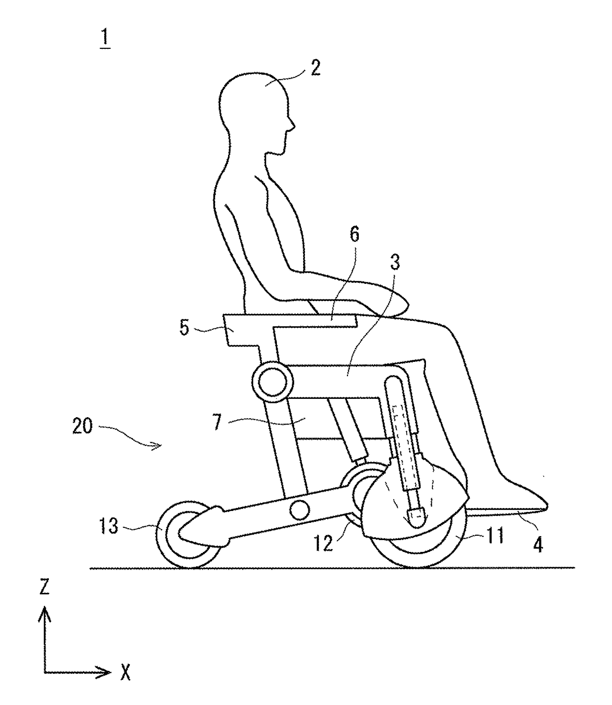
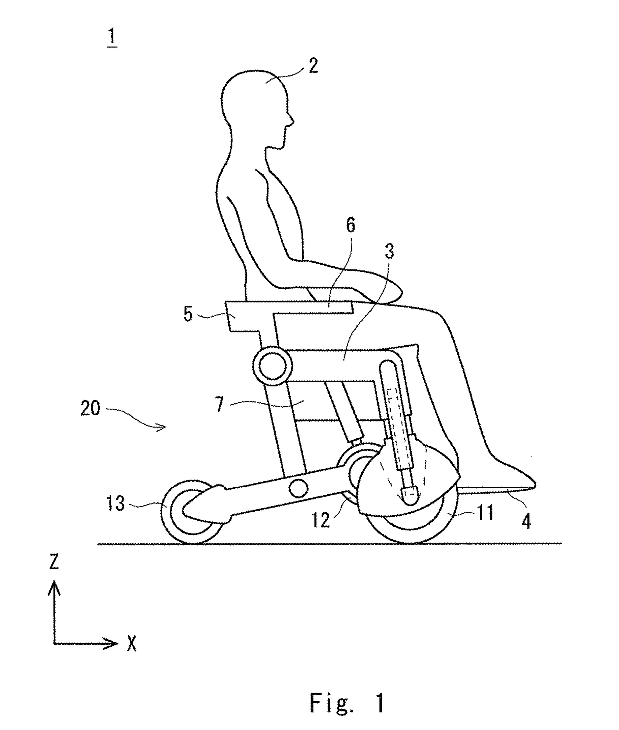
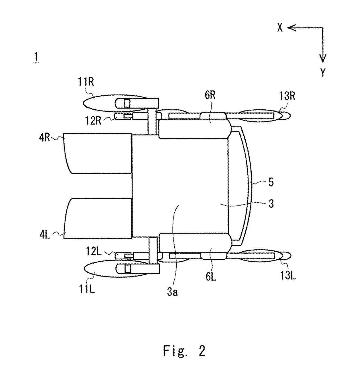
[0039]A vehicle, which is an example of a travelling apparatus according to this exemplary embodiment, will be described by referring to FIGS. 1 and 2. FIG. 1 is a side view showing a structure of a vehicle 1, and FIG. 2 is a top view showing the structure of the vehicle 1. An XYZ Cartesian coordinate system is used for the description of FIGS. 1 and 2. The +X direction is a front of the vehicle 1, and the −X direction is a back of the vehicle 1. Further, the +Y direction is a left direction of the vehicle 1, and the −Y direction is a right direction of the vehicle 1. The +Z direction is vertically upward, and the −Y direction is vertically downward.

[0040]As shown in FIG. 1, the vehicle 1 includes a riding seat 3, footrests 4, a backrest 5, armrests 6, a control box 7, front wheels 11, middle wheels 12, rear wheels 13, and a variable mechanism 20. Note that the vehicle 1 has a symmetric structure and includes the footrests 4, the armrests 6, the front wheels...

second exemplary embodiment

[0134]A travelling apparatus according to a second exemplary embodiment will be described by referring to FIG. 15. Also in this exemplary embodiment, the travelling apparatus described is a vehicle similar to that of the first exemplary embodiment. FIG. 15 is a model diagram showing a structure of a variable mechanism of a travelling apparatus according to the second exemplary embodiment. In this exemplary embodiment, the structure of the variable mechanism differs from the first exemplary embodiment. In the second exemplary embodiment, a position where the third linear motion mechanism 26 is attached differs from the first exemplary embodiment. As the structure other than the third linear motion mechanism 26 is the same as that of the first exemplary embodiment, description thereof will be omitted.

[0135]The third linear motion mechanism 26 is provided in an extendable and retractable manner between the first linear motion mechanisms 22 and the rear links 24. To be more specific, on...


PUM


Abstract

The travelling apparatus according to exemplary embodiments includes front wheels, which are driving wheels, an upper frame, first linear motion mechanisms configured to be extendable and retractable and couple the front wheels to the upper frame, middle wheels configured to be disposed at a back of the front wheels, second linear motion mechanisms configured to be extendable and retractable and couple a riding part to the middle wheels, rear wheels configured to be disposed at a back of the middle wheels, lower links configured to couple the middle wheels to the rear wheels, respectively, rear links configured to couple the lower links to the upper frame, and a third linear motion mechanism configured to change an angle between the upper frame and the rear links.

Description

TECHNICAL FIELD[0001]The present invention relates to a travelling apparatus.BACKGROUND ART[0002]Vehicles for the elderly and the disabled such as electric wheelchairs and mobility scooters are not suitable for uneven terrains, slopes, and large steps. Wheelchairs are difficult to get on escalators. Further, mobility scooters cannot be brought on trains and buses. As there are concerns about accidents where mobility scooters fall sideways, the mobility scooters are not suitable for usage environments where steps and slopes are present on the sides of the mobility scooters, and thus the mobility scooters need to travel at a low speed in order to travel safely.[0003]Patent Literature 1 discloses a wheelchair that can ascend and descend stairs. The wheelchair disclosed in Patent Literature 1 includes six wheels. Right and left front wheels are driving wheels. Two other wheels are arranged on one side of the wheelchair behind the right and left front wheels. The six-wheel grounded state...

Claims


Application Information

Patent Timeline
IPC IPC(8): A61G5/06A61G5/04
CPCA61G5/06A61G5/061A61G5/04A61G5/042A61G5/068A61G5/1059
Inventor ISHIKAWA, MASARUMATSUMOTO, KIYOSHITAKAHATA, TOMOYUKISHIMOYAMA, ISAOIZUO, TAKASHIKUROKI, YOSHIHIROTAKAHASHI, TAROKOSAKA, YUSUKE
Owner THE UNIV OF TOKYO
Why Eureka
Try Eureka