
Continuous kneading device

a kneading device and continuous technology, applied in the direction of mixing, transportation and packaging, rotary stirring mixers, etc., can solve the problems of kneading load adversely affecting the kneading rotor or bearing, kneading rotors to be further increased, kneading rotors to be kneading, etc., to achieve sufficient knead

Active Publication Date: 2017-06-22
KOBE STEEL LTD
View PDF5 Cites 1 Cited by
  • Summary
  • Abstract
  • Description
  • Claims
  • Application Information

AI Technical Summary

Benefits of technology

The present invention provides a continuous kneading device with two kneading rotors that can have a larger space between them while still being able to handle heavy loads. This device can effectively knead even the most difficult materials.

Problems solved by technology

The kneading load can adversely affect the kneading rotors or bearing that supports the kneading rotors, or the like.
For the reason, the conventional continuous kneading device cannot allow the mesh between the kneading rotors to be further increased, which brings the difficulty in adapting the continuous kneading device to a kneading resistant material.

Method used


Image

  • Continuous kneading device
  • Continuous kneading device
  • Continuous kneading device

Examples


examples

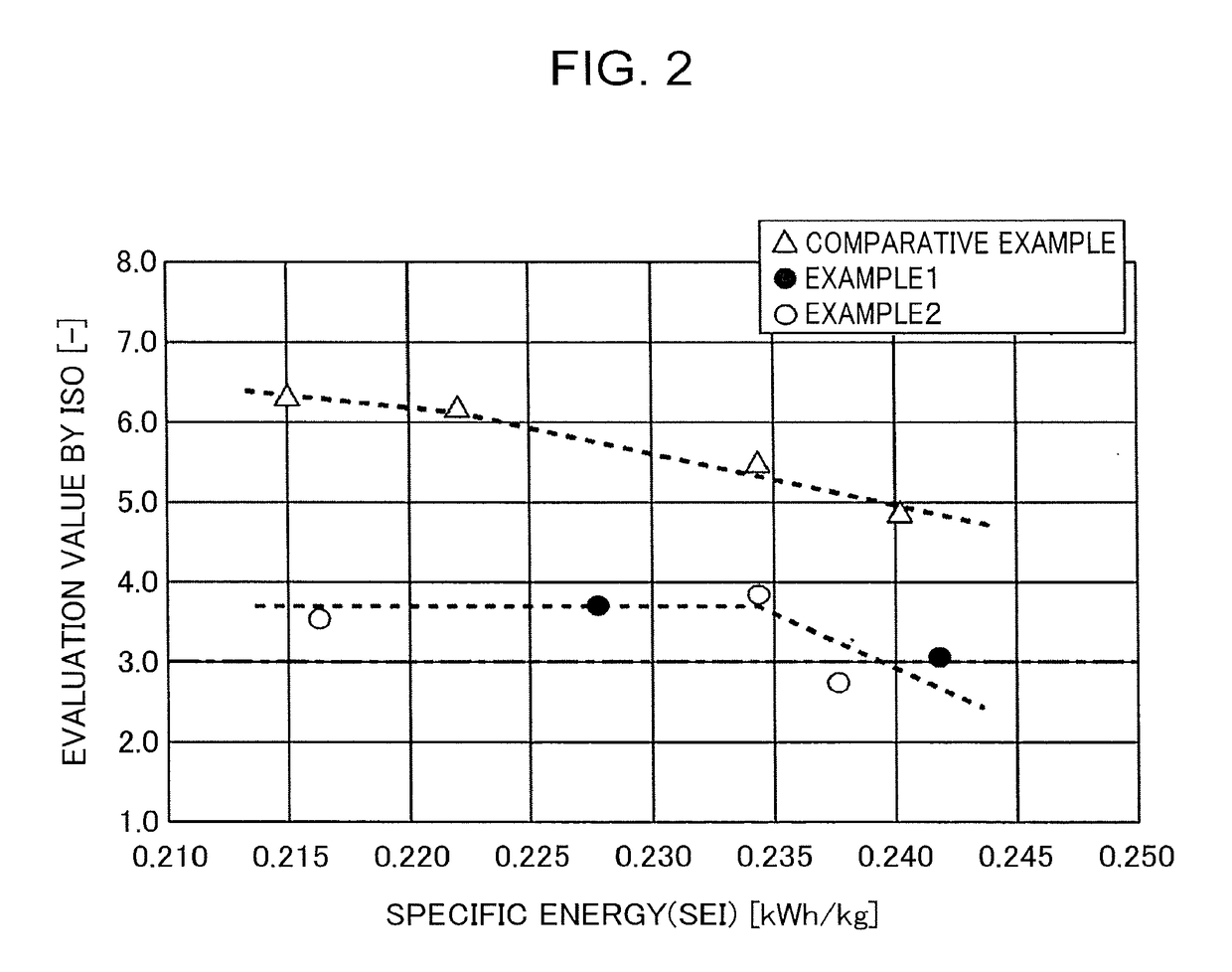
[0041]Next will be explained the action and effects of the continuous kneading device 1 according to the embodiment more specifically in comparison with a comparative example.

[0042]In each of Example 1, Example 2, and Comparative example explained below, kneaded is a hard-to-knead material, HDPE (high-density polyethylene resin), by a processing amount of 520 kg / h. The material is kneaded until specific energy which has been applied to the material reach approximately 0.240 kWh / kg. The continuous kneading device according to each of Example 1, Example 2, and Comparative example has, as shown in Table 1, a rotational outer diameter of the kneading rotors 3 (“rotor outer diameter” shown in the table), an inner diameter of the barrel 2 (“chamber inner diameter” shown in the table), an inter-axis distance, and a chip clearance. The rotor outer diameter D11 and the rotor outer diameter D21 shown in Table 1 are equivalent to the rotational outer diameter D1 of each of the kneading flights...


PUM

PropertyMeasurementUnit
rotational outer diameter D2aaaaaaaaaa
rotational outer diameter D1aaaaaaaaaa
shearing forcesaaaaaaaaaa

Abstract

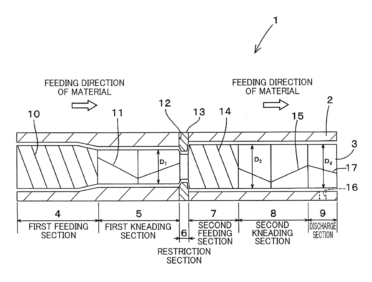
A continuous kneading device (1) includes a pair of kneading rotors (3), being capable of increasing mesh between the kneading rotors (3) while suppressing a kneading load applied to the kneading rotors (3). The continuous kneading device (1) includes a barrel (2) and a pair of kneading rotors (3) housed in the barrel (2) and rotating in mesh in directions different from each other. Each kneading rotor (3) includes a plurality of kneading flights (11, 15) for kneading a material supplied into the barrel (2). The kneading flights (11, 15) and respective portions of the barrel (2) housing the kneading flights (11, 15) respectively configure a plurality of kneading sections aligned axially of the kneading rotors (3). The material is fed axially from the upstream kneading section to the downstream kneading section to be sequentially kneaded. The kneading flight (15) constituting the downstream kneading section has a rotational outer diameter (D2) larger than a rotational outer diameter (D1) of the kneading flight (11) constituting the upstream kneading section.

Description

TECHNICAL FIELD[0001]The present invention relates to a continuous kneading device that continuously kneads a material such as resin.BACKGROUND ART[0002]As a continuous kneading device that continuously kneads a material such as resin, there has been a continuous kneading device disclosed in Patent Literature 1, or the like. The continuous kneading device of Patent Literature 1 includes an internally hollowed barrel and a pair of kneading rotors housed in the barrel. The pair of kneading rotors is disposed so as to make their respective axes be substantially parallel to each other and allowed to rotate in respective directions different from each other. In the continuous kneading device, a material supplied into the barrel is led to between the kneading rotors rotating in the directions different from each other and kneading screws provided in the kneading rotors apply shearing forces to the material to thereby knead the material.[0003]In recent years, it is required to knead a hard...

Claims


Application Information

Patent Timeline
Patent Type & Authority Applications(United States)
IPC IPC(8): B01F7/08B01F7/00B29C48/52
CPCB01F7/082B01F2215/0049B01F7/00891B29B7/489B29B7/488B29C48/268B29C48/402B29C48/52B29C48/54B29C48/55B29C48/57B29C48/682B29B7/483B29C48/41B29B7/482B01F27/421B01F27/722B01F2101/2805
Inventor YAMAGUCHI, KAZUOKURODA, YOSHINORIFUNAHASHI, HIDEOFUKUI, TSUGUSHI
Owner KOBE STEEL LTD
Learn More