Drying device, printing apparatus, and drying method

a printing apparatus and drying device technology, applied in printing, other printing apparatus, etc., can solve the problems of increasing the manufacturing cost of the printing apparatus, adverse effects on a different place in the apparatus, and increasing the humidity inside the apparatus, so as to reduce the temperature drop of the heat roller, reduce the humidity increase, and increase the drying efficiency

Active Publication Date: 2017-06-22
DAINIPPON SCREEN MTG CO LTD
View PDF3 Cites 20 Cited by
  • Summary
  • Abstract
  • Description
  • Claims
  • Application Information

AI Technical Summary

Benefits of technology

[0010]According to the present invention, high-temperature gas with heat absorbed from the part near the heat source is fed to the surrounding of the heat roller. This reduces humidity increase in the surrounding of the heat roller and reduces temperature drop of the heat roller, compared to feeding gas at ordinary temperature. As a result, drying efficiency is increased. Further, diffusion of the high-temperature gas in the printing apparatus is reduced.

Problems solved by technology

However, if the gas brought to high temperature by absorption of heat from the member diffuses in the printing apparatus, temperature inside the apparatus may be increased to cause adverse effect on a different place in the apparatus.
However, adding the temperature adjusting mechanism substantially increases manufacturing cost for the printing apparatus.
However, supplying gas at ordinary temperature to the neighborhood of the surface of the heat roller reduces the temperature of the heat roller.
This may work contrarily to reduce drying efficiency.

Method used


Image

  • Drying device, printing apparatus, and drying method
  • Drying device, printing apparatus, and drying method
  • Drying device, printing apparatus, and drying method

Examples


Embodiment Construction

[0018]A preferred embodiment according to the present invention will now be described with reference to the drawings.

[0019]

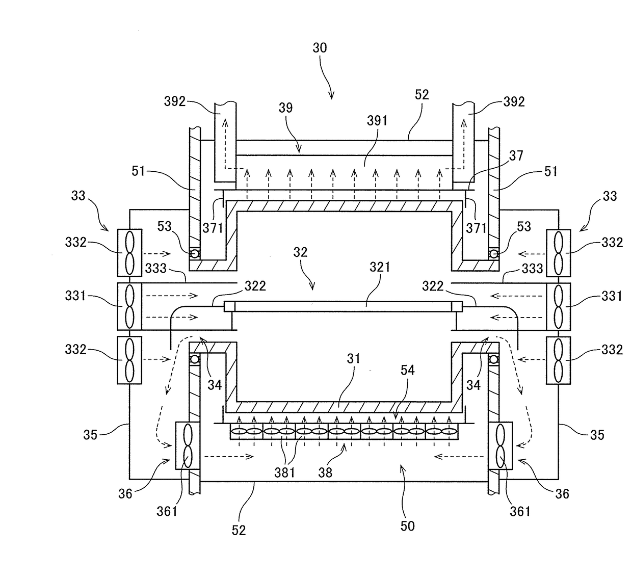
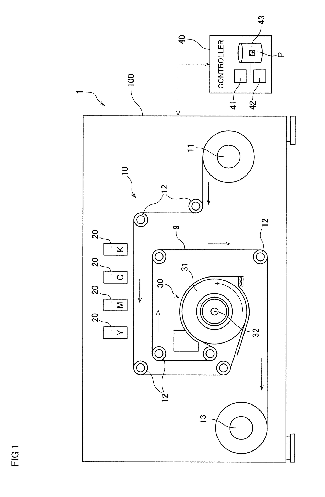
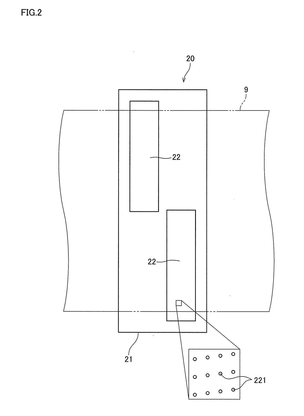
[0020]FIG. 1 shows the configuration of a printing apparatus 1 according to one preferred embodiment of the present invention. The printing apparatus 1 is an apparatus that records an image on a surface of printing paper 9 that is an elongated strip-shaped printing medium by an inkjet system while transporting the printing paper 9. As shown in FIG. 1, the printing apparatus 1 includes a transport mechanism 10, four head units 20, a drying device 30, and a controller 40. The transport mechanism 10, the four head units 20, and the drying device 30 are housed in an outer housing 100 of the printing apparatus 1.

[0021]The transport mechanism 10 is a mechanism for transporting the printing paper 9 in a transport direction along the length of the printing paper 9. The transport mechanism 10 of the preferred embodiment includes an unwinding roller 11, a plurality of tra...


PUM


Abstract

A drying device includes a cooling unit, a gas outward guide unit, a gas inward guide unit, a gas supply unit, and a gas exhaust unit. The cooling unit feeds cooling wind toward a part near a heat source. The gas outward guide unit guides gas outwardly from the part near the heat source. The gas inward guide unit guides the outwardly-guided gas inwardly into the drying chamber. The gas supply unit supplies the inwardly-guided gas in the drying chamber to a neighborhood of an outer peripheral surface of the heat roller. The gas exhaust unit releases gas from a surrounding of the heat roller to the outside of a printing apparatus. Thus, high-temperature gas with heat absorbed from the part near the heat source is fed to the surrounding of the heat roller. This reduces humidity increase in the surrounding of the heat roller and reduces temperature drop of the heat roller, compared to feeding gas at ordinary temperature. Further, diffusion of the high-temperature gas in the printing apparatus is prevented.

Description

BACKGROUND OF THE INVENTION[0001]Field of the Invention[0002]The present invention relates to a drying device that dries ink adhering to an elongated strip-shaped printing medium, a printing apparatus including the drying device, and a drying method of drying ink adhering to an elongated strip-shaped printing medium.[0003]Description of the Background Art[0004]In a printing apparatus conventionally known, an image is recorded on elongated strip-shaped printing paper by ejecting ink toward the printing paper while the printing paper is transported in its longitudinal direction. Some printing apparatus of this type includes a drying mechanism employing a heat roller system. The drying mechanism employing the heat roller system heats and dries ink by making printing paper contact a surface of a heated heat roller.[0005]The conventional printing apparatus including the drying mechanism employing the heat roller system is described in Japanese Patent Application Laid-Open No. 2015-178230...

Claims


Application Information

Patent Timeline
Patent Type & Authority Applications(United States)
IPC IPC(8): B41J11/00
CPCB41J11/002B41J29/377B41J29/38B41J11/0024
Inventor TSUTSUI, YUKINISHIMURA, HIROTAKE
Owner DAINIPPON SCREEN MTG CO LTD
Why Eureka
Try Eureka