
Blade assembly on basis of a modular structure for a turbomachine

Inactive Publication Date: 2017-06-22
ANSALDO ENERGIA IP UK LTD
View PDF0 Cites 30 Cited by
  • Summary
  • Abstract
  • Description
  • Claims
  • Application Information

AI Technical Summary

Benefits of technology

The patent describes a blade design for a turbomachine that allows for easy replacement of parts without replacing the whole blade. The blade consists of an airfoil and an inner platform that can be separated. This design allows for the use of different materials in the blade shell, depending on the operating regime of the turbomachine. Overall, the patent describes a more flexible and adaptable design for blades in turbomachines.

Problems solved by technology

If the blade airfoil is internally cooled with a cooling medium at a higher pressure than the hot combustion gases, excessive cooling medium leakage into the hot gas path can occur.

Method used


Image

  • Blade assembly on basis of a modular structure for a turbomachine
  • Blade assembly on basis of a modular structure for a turbomachine
  • Blade assembly on basis of a modular structure for a turbomachine

Examples


Embodiment Construction

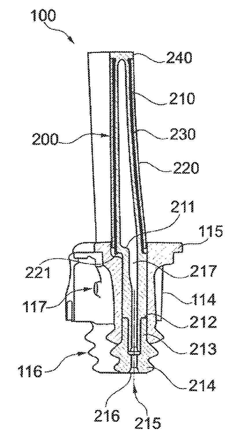
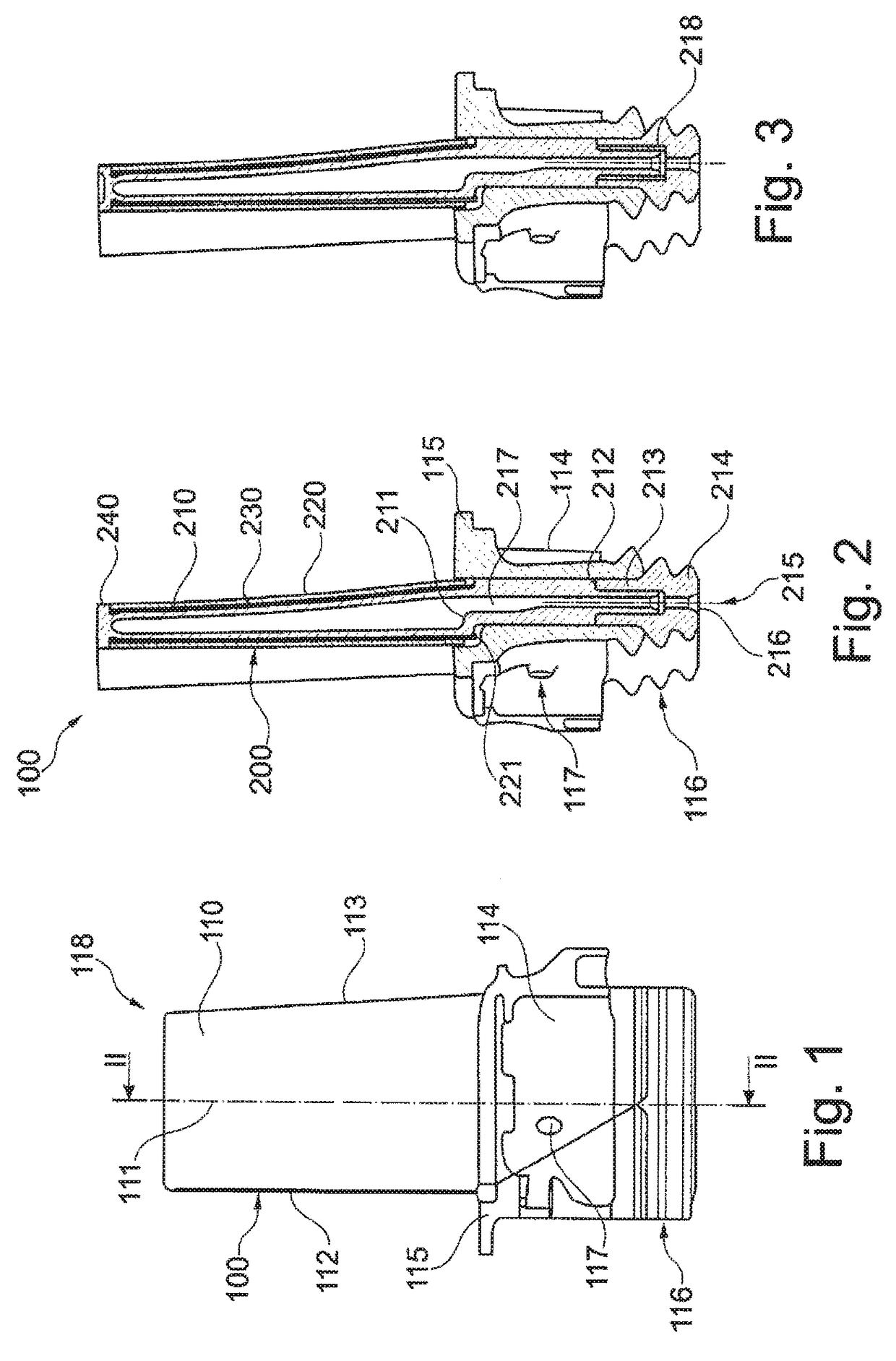
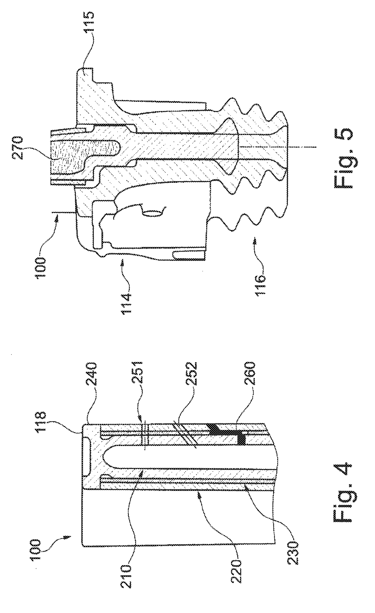
[0095]In FIG. 1 a rotor blade 100 according to an exemplary embodiment of the invention is reproduced. The rotor blade 100 comprises a blade airfoil 110 which extends in the longitudinal direction of the rotor blade along a longitudinal axis 111. The blade airfoil 110, which is delimited by a leading edge 112 and a trailing edge 113 in the flow direction, merges into a shank 114 at the lower end beneath an inner platform 115 which forms the inner wall of the hot gas passage, the shank is terminating in a customary blade root 116 with a fir tree profile by which the blade 100 can be fastened on a blade carrier, especially on a rotor disk, by inserting it into a corresponding axial slot.

[0096]The inner platform abuts the platforms of neighboring blades and defines a gas passage inner wall for the turbine. A row of outer not shown heat shields at the tip of the blade airfoil 118 defines the outer wall of the hot gas path of the gas turbine.

[0097]Cooling passages, which are not shown, e...


PUM

PropertyMeasurementUnit
Fractionaaaaaaaaaa
Areaaaaaaaaaaa
Thermal stressaaaaaaaaaa

Abstract

A blade assembly having a modular structure, wherein the blade elements include at least a rotor blade airfoil, a footboard mounting part and a heat shield. The elements each have at its one ending an interchangeable connection for connection among each other, wherein the connection of the airfoil with respect to the other elements is based on a fixation in radial or quasi-radial extension compared to the rotor axis of the turbomachine. The assembling of the blade airfoil in connection with the footboard mounting part is based on a force-fit or form-fit fixation, or on use of a metallic and / or ceramic surface for the purpose of a friction-locked bonding actuated by adherence interconnecting, or on friction-locking with a detachable, permanent or semi-permanent fixation.

Description

TECHNICAL FIELD[0001]The present invention relates to a blade assembly for a turbomachine, preferably a gas turbine engine, and basically refers to a modular rotor blade with one or more removable elements or modules. The term blade is to define in a broad sense and includes also stator vanes, heat shields, etc.[0002]Basically, the modular blade assembly comprises various interchangeable modules or elements, wherein the mentioned parts are substitutable or non-substitutable.[0003]A blade assembly on the basis of a modular structure is provided and includes a blade airfoil which extends in a blade longitudinal direction and at the lower end merges, optionally, into an inner platform or other intermediate embodiments and, subsequently, terminating in a customary blade root with preferentially a fir-tree-shaped cross-sectional profile by which the blade can be fastened on a blade carrier, in case of a rotor blade on a rotor disk, wherein the blade airfoil and / or the inner platform or o...

Claims


Application Information

Patent Timeline
IPC IPC(8): F01D5/14F01D5/28F01D5/18F02C3/04F01D15/10
CPCF01D5/147F02C3/04F01D15/10F01D5/187F05D2300/20F01D5/288F05D2220/32F05D2230/60F05D2300/10F01D5/186F05D2230/51F05D2240/40
Inventor FERBER, JOERGENHOEVEL, SIMONEOPDERBECKE, THOMASYAKUSHKOV, DMITRYDROZDOV, ALEXEY
Owner ANSALDO ENERGIA IP UK LTD
Features
  • Generate Ideas
  • Intellectual Property
  • Life Sciences
  • Materials
  • Tech Scout
  • Unparalleled Data Quality
  • Higher Quality Content
  • 60% Fewer Hallucinations
Learn More