Locating a portable device based on coded light

a portable device and coded light technology, applied in the field of location systems, can solve the problems of “clearly visible edges and system performance problems, and achieve the effect of accurate location and reduced cos

Active Publication Date: 2017-06-22
SIGNIFY HLDG BV
View PDF1 Cites 10 Cited by
  • Summary
  • Abstract
  • Description
  • Claims
  • Application Information

AI Technical Summary

Benefits of technology

[0015]In a preferred embodiment the portable device may, once it has established its position relative to a coded light source, also use other light sources, more particularly non-coded light sources for localization. To this end the method further comprises obtaining heading information indicative of the orientation of the portable device in the horizontal plane, obtaining a second image comprising a second light source. Notably the second light source may, but need not, transmit coded light. In the event that the second light source emits coded light it may be possible to use that information as described hereinbefore to determine the device location. By combining the newly calculated location with the previous calculated location a more accurate location can be obtained.
[0016]In the event that the second light source does not emit coded light it may still be possible to use the detection of that light source in combination with the previously calculated location and the information from the IMU to compute a reliable location update. To this end the earlier described method may be extended by, accessing second map information comprising three dimensional location data, providing further three-dimensional locations of light sources, establishing a candidate light source comprised in the second map information based on a computed location of the portable device or image sensor, the position of the second light source in the second image, and the heading information, and computing an updated location of the portable device or image sensor under the assumption that the light source in the second image corresponds with the candidate light source, using: the orientation information, the position of the second light source in the second image, the location of the candidate light source in the second image, the predetermined height estimate of the portable device or image sensor, and the location of the candidate light source identified by the second map information. As in this approach both coded light sources and non-coded light sources can be used this approach enables localization using coded light at a reduced cost for existing locations, as only some of the light sources need to be replaced by coded-light light sources.

Problems solved by technology

However, not all ceilings have such “clearly visible edges”, and in situations where these are lacking the system may not perform well.

Method used


Image

  • Locating a portable device based on coded light
  • Locating a portable device based on coded light
  • Locating a portable device based on coded light

Examples


Embodiment Construction

[0048]The present invention will now be described more fully hereinafter with reference to the accompanying drawings. The below embodiments are provided by way of example so as to convey the scope of the invention to those skilled in the art. Like numbers refer to like elements throughout.

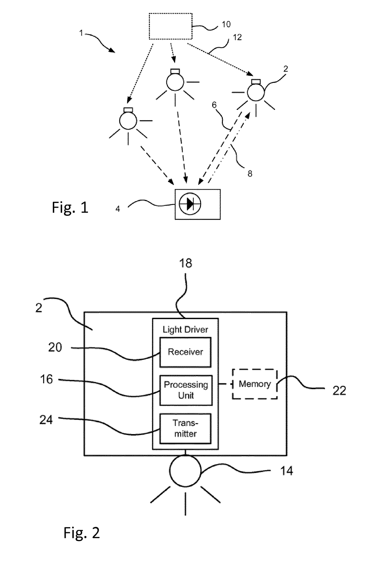
[0049]Coded light systems as such are known. FIG. 1 illustrates a lighting system 1 comprising at least one light source, schematically denoted by the reference numeral 2. The at least one light source 2 may be a luminaire and / or be part of a lighting control system. Each light source 2 is capable of emitting coded light, as schematically illustrated by the arrow 6. Thus the lighting system 1 may be denoted as a coded light lighting system. A luminaire may comprise at least one light source 2. The term “light source” means a device that is used for providing light in a room, for purpose of illuminating objects in the room. A room is in this context typically an apartment room or an office room, a g...


PUM


Abstract

The invention relates to an apparatus, a system and a method of locating a location of a portable device using coded light, the portable device comprising an image sensor and an inertial measurement unit, the method comprising: obtaining a first image comprising the coded light source from the image sensor and substantially simultaneously obtaining orientation information indicative of the orientation of the portable device or the image sensor from the inertial measurement unit; obtaining light source specific information in the form of: an identifier that allows retrieval of a three-dimensional location of the coded light source or a three-dimensional location of the coded light source; and computing the location of the portable device or image sensor based on the orientation information, a predetermined height estimate of the portable device or image sensor and the light source specific information.

Description

FIELD OF THE INVENTION[0001]The present invention relates generally to the field of location systems, and more particularly to a method, apparatus and system for localization based on coded light.BACKGROUND OF THE INVENTION[0002]Location systems have become mainstream devices in the last two decades, first with the introduction of low-cost GPS devices and later on with the almost worldwide adoption of smart phones having navigation functionality.[0003]More recently indoor location systems are receiving increased attention. Several indoor location systems are known, systems based on, infrared (IR), ultrasound, video surveillance, and RF signals.[0004]Also multi-modal systems appear to attract quite some attention, such as the “Headio” system, as presented in “Headio: Zero-Configured Heading Acquisition for Indoor Mobile Devices Through Multimodal Context Sensing”, by Zheng Sun, et al. The latter system combines information from gravity sensors and magnetometer sensors as found in a s...

Claims


Application Information

Patent Timeline
Patent Type & Authority Applications(United States)
IPC IPC(8): G06T7/73G06F1/16
CPCG06T7/74G06F1/1686H04M1/0202G06T2207/30244G06F1/1694G06F3/0346G01C21/206G01S5/16
Inventor BAGGEN, CONSTANT PAUL MARIE JOZEFHOEKSTRA, PETERVOS, BENJAMIN JOHANNESVAN TIEL, BAS
Owner SIGNIFY HLDG BV
Why Eureka
Try Eureka