Liquid flow control based upon energy balance and fan speed for controlling exhaust air temperature

a technology of energy balance and fan speed, applied in the field of information handling system, can solve the problems of greater heat dissipation per node, requiring more directed cooling solutions,

Active Publication Date: 2017-06-22
DELL PROD LP
View PDF10 Cites 23 Cited by
  • Summary
  • Abstract
  • Description
  • Claims
  • Application Information

AI Technical Summary

Benefits of technology

[0008]The illustrative embodiments of the present disclosure provide a direct-injection liquid cooled (DL) rack information handling syst...

Problems solved by technology

The amount of processing capacity and storage capacity per node and/or per rack continues to in...

Method used


Image

  • Liquid flow control based upon energy balance and fan speed for controlling exhaust air temperature
  • Liquid flow control based upon energy balance and fan speed for controlling exhaust air temperature
  • Liquid flow control based upon energy balance and fan speed for controlling exhaust air temperature

Examples


Embodiment Construction

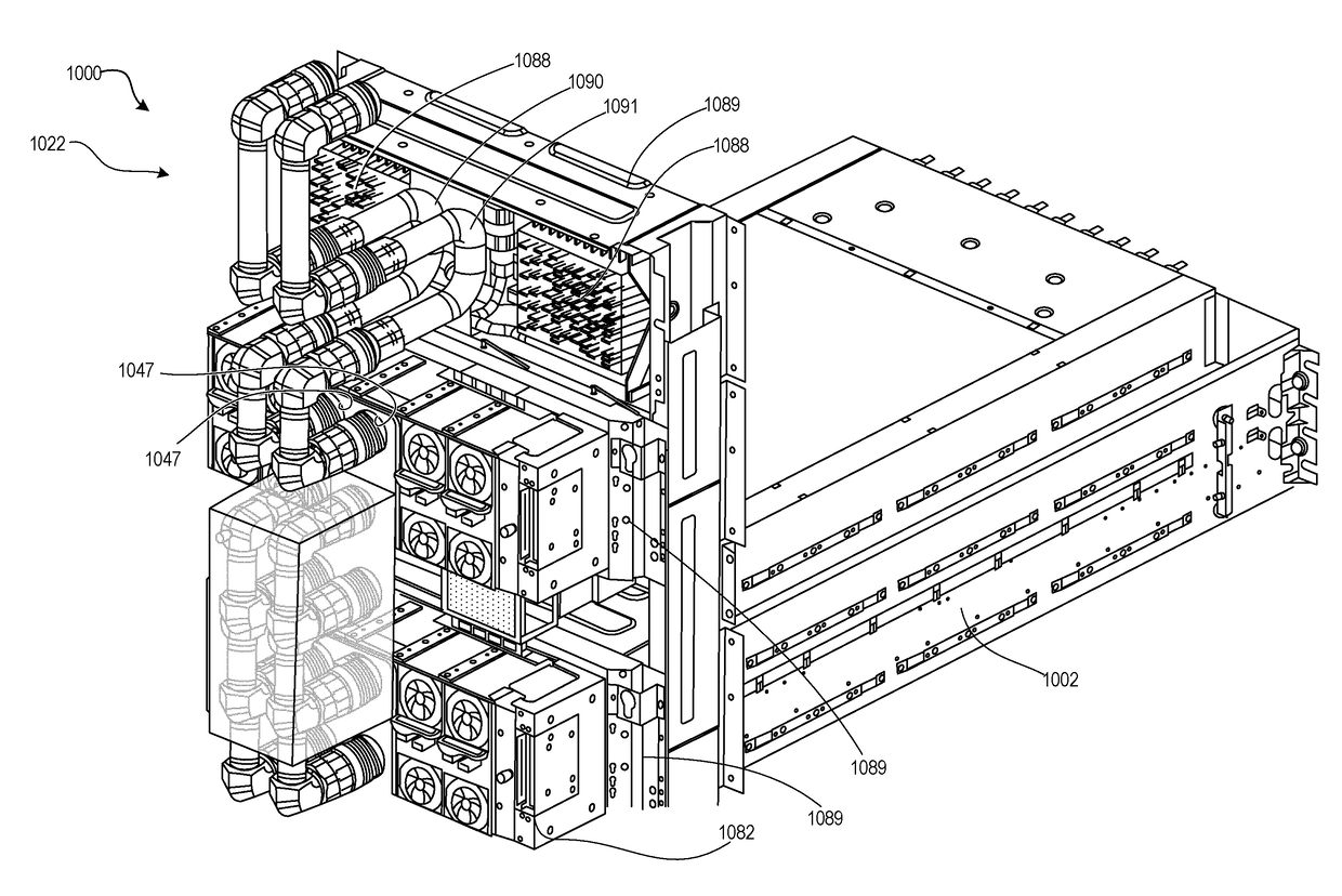
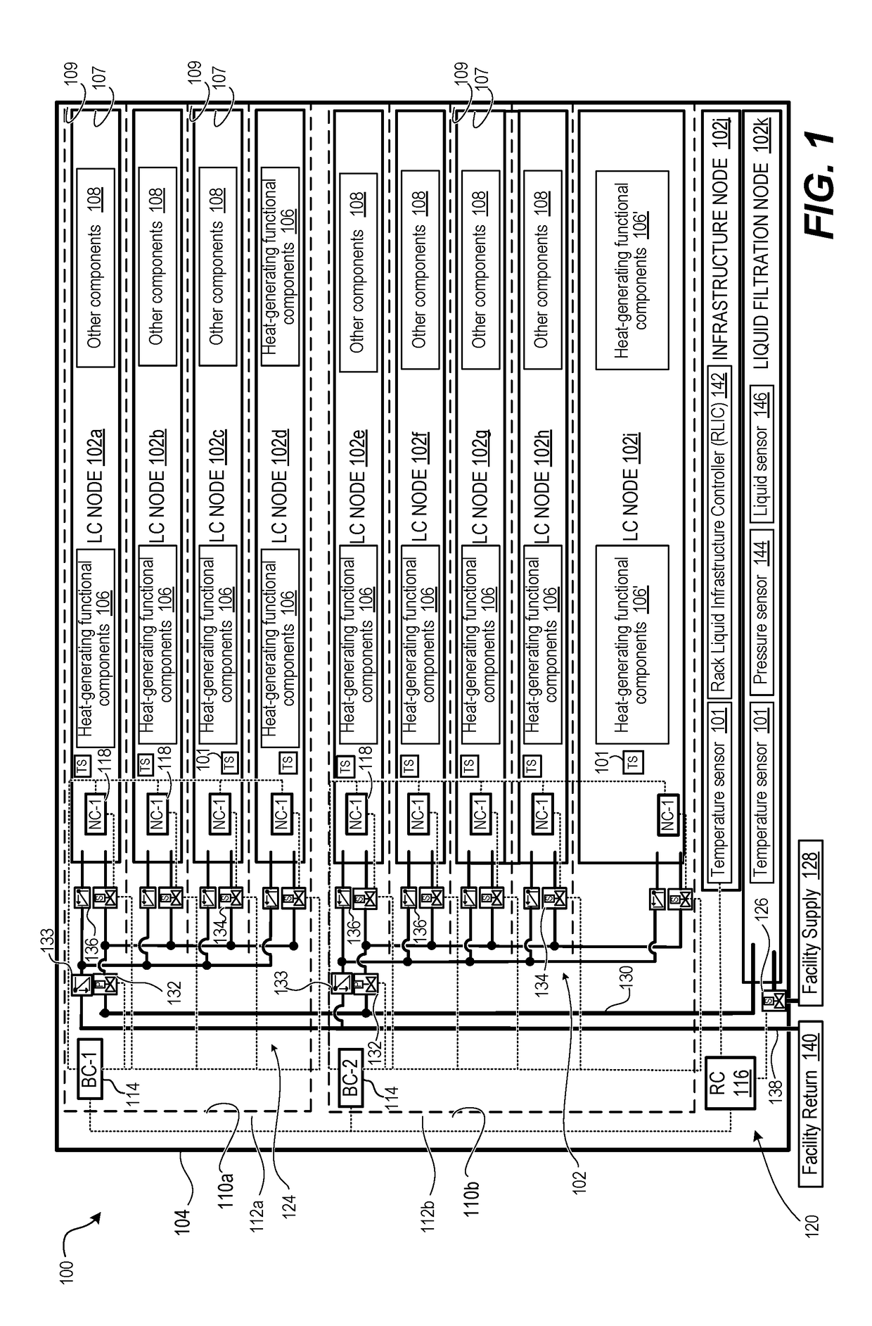
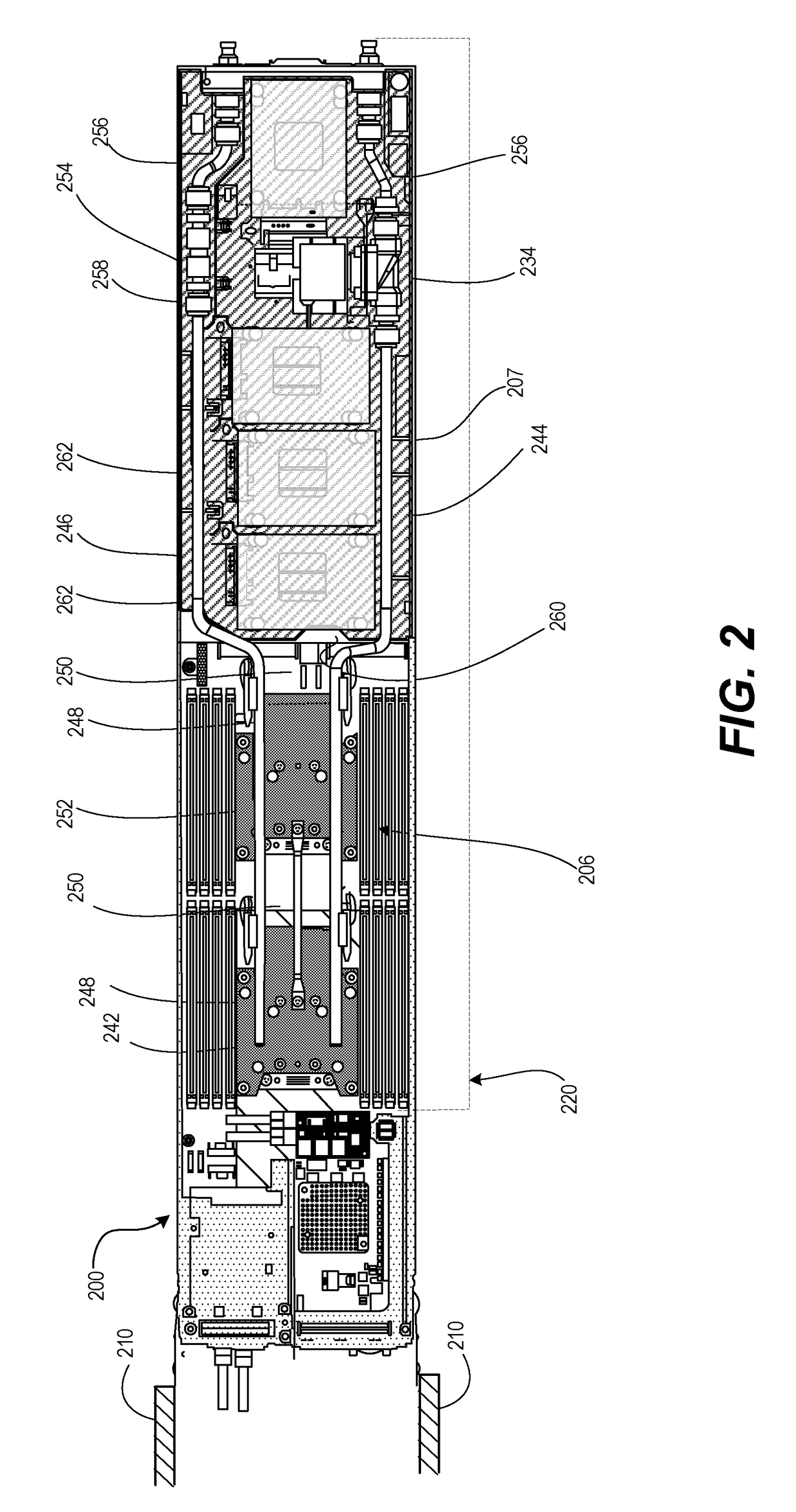
[0031]The present disclosure generally provides a Direct-Interface Liquid-Cooled (DL) Rack Information Handling System (RIHS) providing liquid cooled (LC) information technology (IT) nodes containing heat-generating functional components and which are cooled at least in part by a liquid cooling subsystem. The RIHS includes a rack configured with chassis-receiving bays in which is received a respective chassis of one of the LC nodes. Each LC node is configured with a system of conduits to receive direct injection of cooling liquid to regulate the ambient temperature of the node. Additionally, each LC node, configured with a system of conduits, provides cooling to the components inside the node by conductively absorbing, via the cooling liquid, heat generated by the heat-generating functional components. The absorbed heat is removed (or transferred away) from within the node to outside of the node and / or the RIHS.

[0032]The present disclosure also provides a computer-implemented method...


PUM


Abstract

A computer-implemented method regulates exhaust air temperature from direct interface liquid-cooled (DL) nodes in a rack information handling system (RIHS). The method includes receiving a first input corresponding to a desired ambient temperature of an exterior space and a second input is corresponding to an amount of heat being dissipated from functional components operating within an interior space of at least one LC node. An ambient temperature reading of the exterior space is received. A flow rate is calculated for liquid flowing through an air-to-liquid heat exchange (ATLHE) subsystem that results in an amount of heat exchange in the ATLHE subsystem, which generates exhaust air at a temperature that causes a change in the ambient temperature towards the desired ambient temperature. The flow rate is dynamically adjusted of the liquid flowing through the ATLHE subsystem to the calculated flow rate.

Description

PRIORITY[0001]The present invention claims priority from each of the following provisional patent applications, with relevant content of each listed provisional application incorporated herein by reference: Provisional Application Ser. No.: 62 / 270,563 (Docket No. 106280.02), with filing date Dec. 21, 2015; Provisional Application Ser. No. 62 / 270,584 (Docket No. 106460.02), with filing date Dec. 22, 2015; and Provisional Application Ser. No. 62 / 270,574 (Docket No. 106284.02), with filing date Dec. 21, 2015.BACKGROUND[0002]1. Technical Field[0003]The present disclosure generally relates to information handling systems (IHS), and more particular to a direct-injection liquid cooled (DL) rack-configured IHS (RIHS). Still more particularly, the disclosure is related to modulating exhaust air temperature using liquid flow control within the RIHS.[0004]2. Description of the Related Art[0005]As the value and use of information continue to increase, individuals and businesses seek additional ...

Claims


Application Information

Patent Timeline
IPC IPC(8): H05K7/20G05B15/02
CPCH05K7/20836G05B15/02H05K7/20736H05K7/20781H05K7/20772G05D7/0629
Inventor SHELNUTT, AUSTIN MICHAELNORTH, TRAVIS C.HELBERG, CHRISTOPHER M.
Owner DELL PROD LP
Why Eureka
Try Eureka