Electrostatic chuck heater

a heater and electric motor technology, applied in the field of electric motors, can solve the problems of not being able to achieve high thermal uniformity, and achieve the effects of improving fine control of the thermal uniformity of the wafer, and high resolution

Active Publication Date: 2017-09-28
NGK INSULATORS LTD
View PDF1 Cites 20 Cited by
  • Summary
  • Abstract
  • Description
  • Claims
  • Application Information

AI Technical Summary

Benefits of technology

[0016]In this case, the first electrode area, the second electrode area, the third electrode area, and the fourth electrode area are preferably arranged in this order from one surface (i.e., the surface resin-bonded to the electrostatic chuck) toward the second surface of the sheet heater. With this configuration, the second electrode area having the jumper wires and the third electrode area having the ground electrode each serve as a heat diffusing layer that diffuses heat of the one or more base heater electrodes in the planar direction. This improves thermal uniformity of a wafer mounted on the electrostatic chuck.
[0017]Additionally, since the heater electrodes are disposed near the electrostatic chuck, the heater electrodes can regulate the temperature with a higher resolution and can finely control the thermal uniformity of the wafer.

Problems solved by technology

As a result, it may not be possible to achieve high thermal uniformity.

Method used


Image

  • Electrostatic chuck heater
  • Electrostatic chuck heater
  • Electrostatic chuck heater

Examples


Embodiment Construction

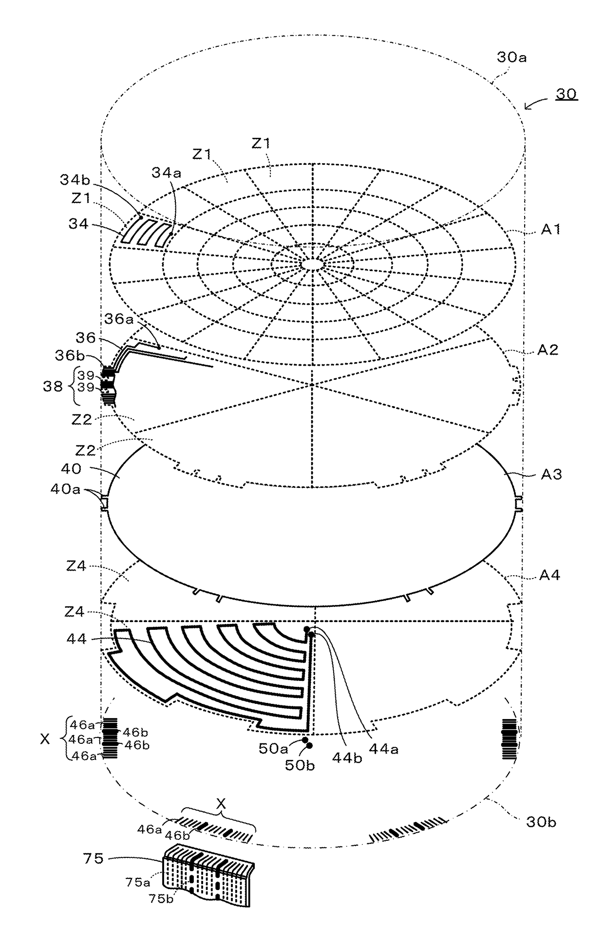
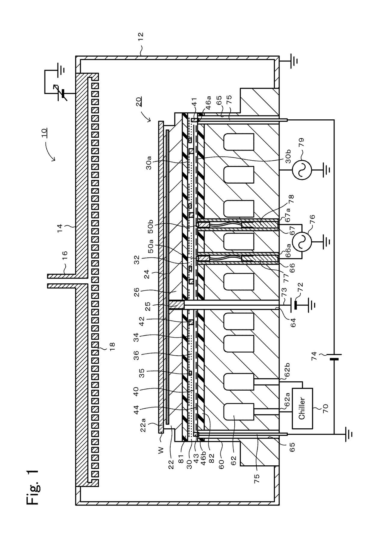
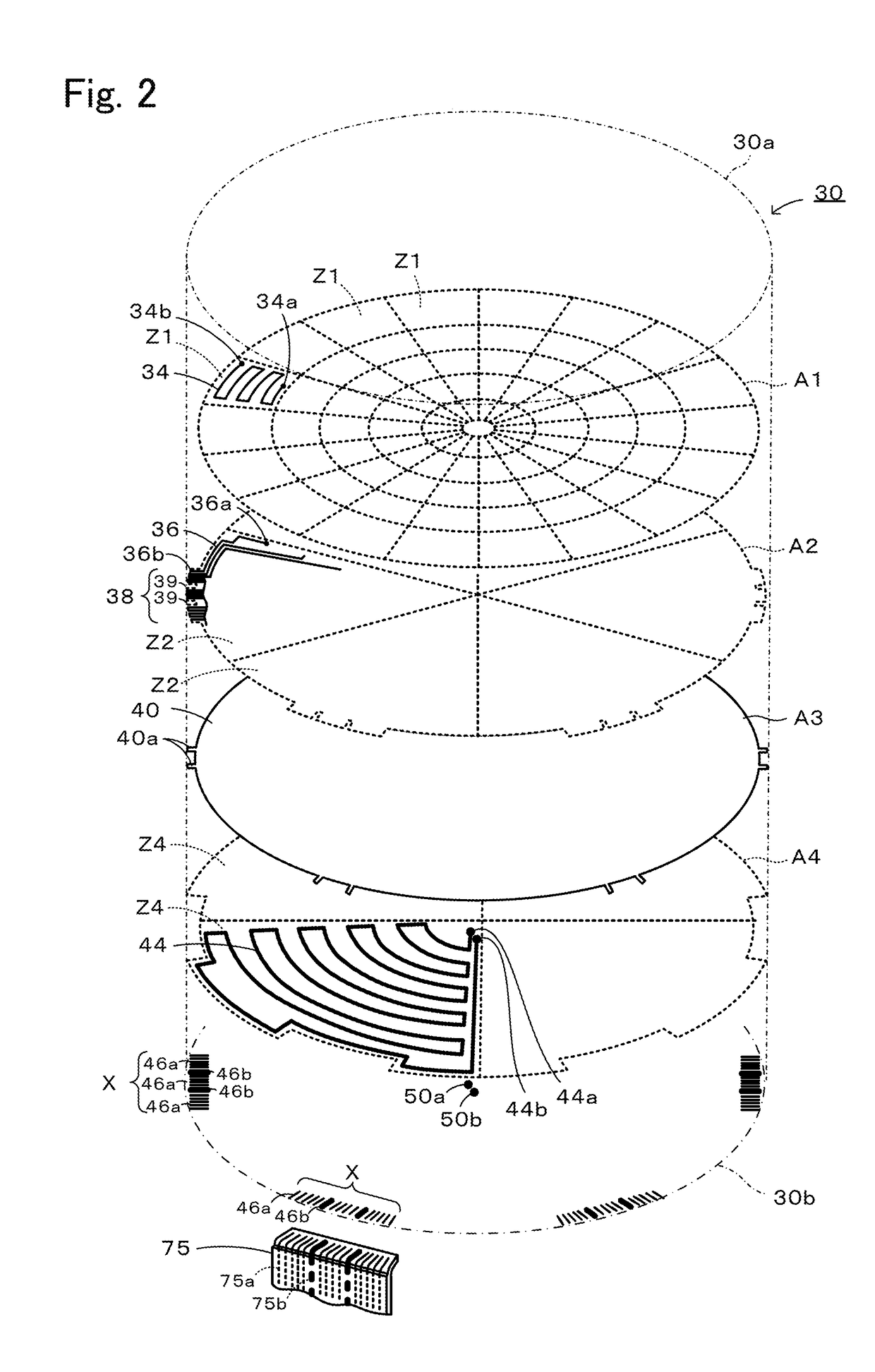
[0023]Preferred embodiments of the present invention will now be described with reference to the drawings. FIG. 1 is a cross-sectional view illustrating a general configuration of a plasma processing apparatus 10. FIG. 2 is a perspective view illustrating an internal structure of a sheet heater 30.

[0024]As illustrated in FIG. 1, the plasma processing apparatus 10, which is a semiconductor manufacturing apparatus, includes a vacuum chamber 12, a shower head 14, and an electrostatic chuck heater 20. The vacuum chamber 12 is a box-shaped container formed of an aluminum alloy or the like. The shower head 14 is attached to a ceiling surface of the vacuum chamber 12. The shower head 14 allows process gas supplied through a gas introducing pipe 16 to be discharged through many gas injection holes 18 into the vacuum chamber 12. The shower head 14 serves as a cathode plate for plasma generation. The electrostatic chuck heater 20 is a device that draws and holds a wafer W onto a wafer mountin...


PUM


Abstract

An electrostatic chuck heater 20 includes an electrostatic chuck 22, a sheet heater 30, and a support pedestal 60. The electrostatic chuck 22 is obtained by embedding an electrostatic electrode 24 in a ceramic sintered body 26. The sheet heater 30 is a resin sheet 32 having a plurality of correction heater electrodes 34 and a plurality of base heater electrodes 44. A first surface of the sheet heater 30 is resin-bonded to the electrostatic chuck 22, and a second surface of the sheet heater 30 is resin-bonded to the support pedestal 60 made of metal.

Description

BACKGROUND OF THE INVENTION1. Field of the Invention[0001]The present invention relates to an electrostatic chuck heater.2. Description of the Related Art[0002]An electrostatic chuck heater is known, which is obtained by bonding a support pedestal made of metal, such as aluminum, to a substrate formed by embedding an electrostatic electrode and a heater electrode in a ceramic sintered body, with a bonding member interposed between the support pedestal and the substrate (see PTL 1). This electrostatic chuck heater is made by stacking a first compact printed with a heater electrode paste on one side, a second compact unprinted on both sides, and a third compact printed with an electrostatic electrode paste on one side, with the printed sides each sandwiched between adjacent compacts, and then calcining and hot-pressing the stacked compacts.CITATION LISTPatent Literature[0003]PTL 1: JP 2013-229310 ASUMMARY OF THE INVENTION[0004]In the process of co-firing the stacked compacts including...

Claims


Application Information

Patent Timeline
Patent Type & Authority Applications(United States)
IPC IPC(8): H05B3/28H01L21/683
CPCH05B3/286H05B2203/016H01L21/6833H01L21/67103H01L21/6831H05B2203/017H01L21/6835H05B3/02H05B3/283
Inventor TAKEBAYASHI, HIROSHI
Owner NGK INSULATORS LTD
Why Eureka
Try Eureka