Turbo-molecular pump

a technology of molecular pump and rotating blade, which is applied in the direction of machines/engines, engine starters, liquid fuel engines, etc., can solve the problems of screw stator and rotor not being able to start rotating, disadvantageous overheating of rotors that include moving blades, and rotors that cannot be rotated. , to achieve the effect of efficient cooling and improving the amount of exhaust flow

Active Publication Date: 2015-03-26
SHIMADZU CORP
View PDF3 Cites 18 Cited by
  • Summary
  • Abstract
  • Description
  • Claims
  • Application Information

AI Technical Summary

Benefits of technology

[0010]The auxiliary ring has a layer which is formed on a surface facing the rotor blade and increases the heat absorption.
[0017]The present invention makes it possible to provide the turbo-molecular pump that prevents the rotor blades from colliding with a reaction product while efficiently cooling the spacers and regulating the temperature of the stator in the screw groove pump section to improve the exhaust flow amount.

Problems solved by technology

However, when discharging a larger amount of gas, the temperature of a rotor that includes the moving blades may disadvantageously exceed an allowable temperature.
As a result, in any place in the turbine blade section and the screw groove pump section, disadvantageously, the moving blades and the stator blades may make contact with each other or the rotor and a screw stator may make contact with each other within a shorter period than a designed life.
Therefore, when a reaction product is accumulated on the screw stator, the screw stator and the rotor may be stuck to each other.
As a result, the rotor may not be able to start rotating.
However, along with an increase in the size of a wafer to be processed, the flow amount of gas that should be discharged by the turbo-molecular pump increases, and the amount of heat generated due to the discharge of gas also increases.
Therefore, a method in which the pump case is cooled as described in Patent Literature 1 does not have enough cooling capacity to cool the stationary blades.
Therefore, heat flowing to the pump case from the base is a factor that inhibits cooling of the stationary blades.
On the other hand, when a turbo-molecular pump has sufficient cooling capacity to cool the stationary blades and the sublimation temperature of a reaction product is higher than the cooling temperature, the reaction product may be accumulated on the inner side of a spacer that corresponds to the bottom step moving blade, and the bottom step moving blade may disadvantageously make contact with the reaction product.

Method used


Image

  • Turbo-molecular pump
  • Turbo-molecular pump
  • Turbo-molecular pump

Examples


first embodiment

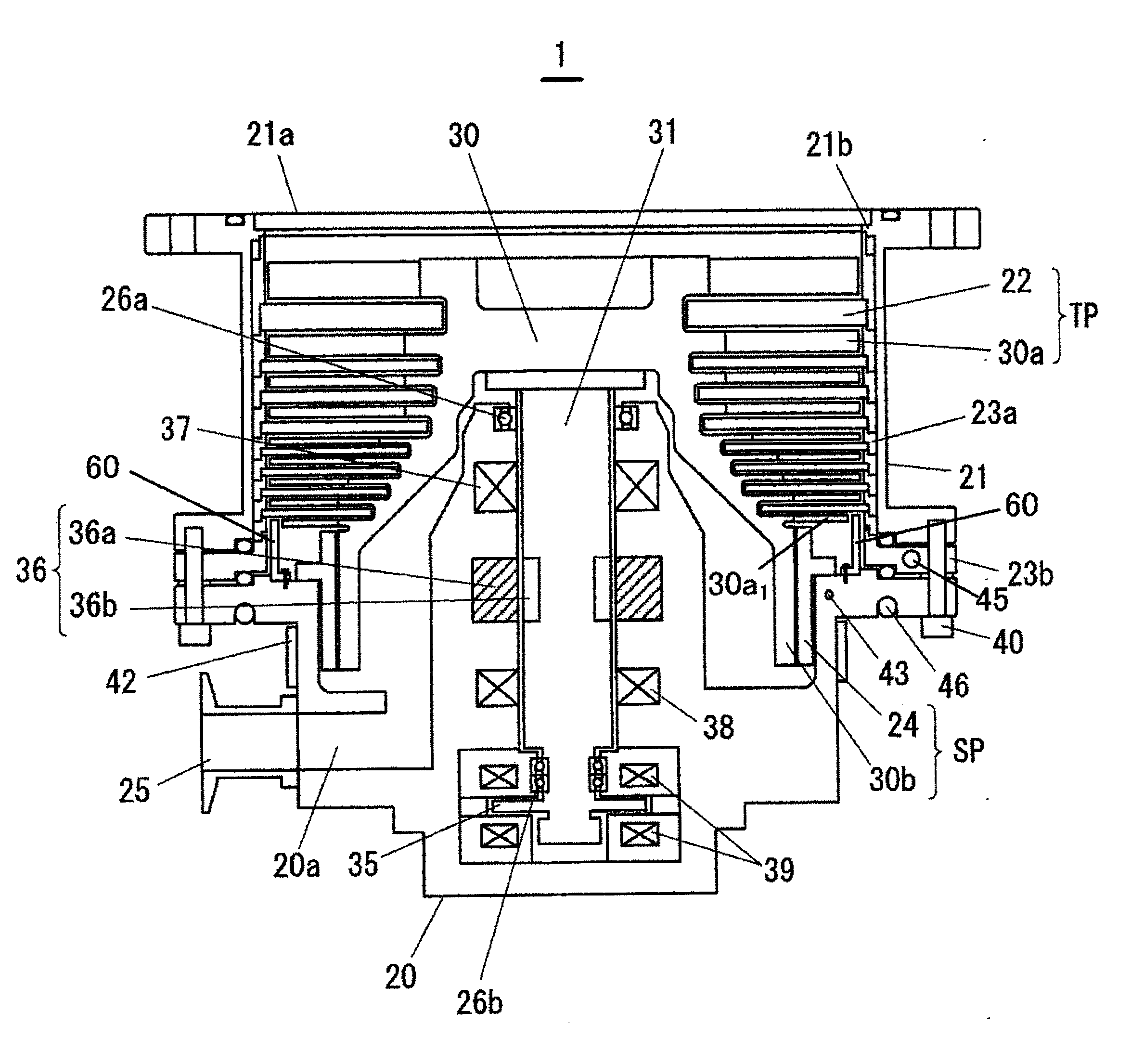
[0032]Hereinbelow, an embodiment of a turbo-molecular pump of the present invention will be described with reference to the drawings. The turbo-molecular pump is provided with a turbine blade section and a screw groove pump section housed inside a pump case. FIG. 1 is a diagram illustrating the schematic configuration of the turbo-molecular pump according to the present invention. The turbo-molecular pump includes a pump main body 1 and a control unit (not illustrated, and described below) which controls the drive of the pump main body 1. The control unit is provided with a main controller which controls the entire pump main body 1, a motor controller which drives a motor 36, a bearing controller which controls magnetic bearings provided in the pump main body 1, a temperature regulation controller 511 (described below, see FIG. 4), and the like.

[0033]In the following description, an active magnetic bearing type turbo-molecular pump will be described as an example. However, the prese...

second embodiment

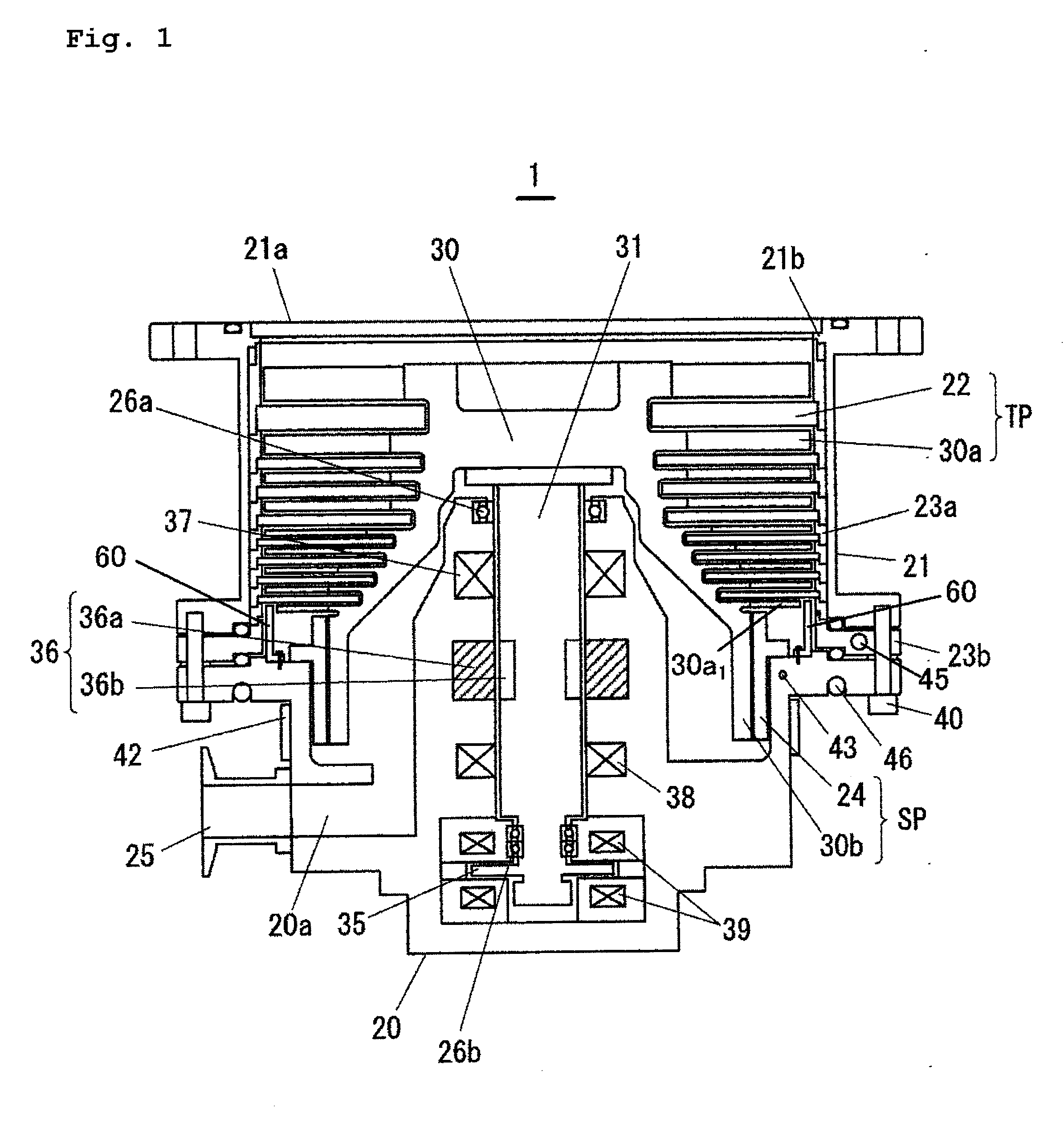
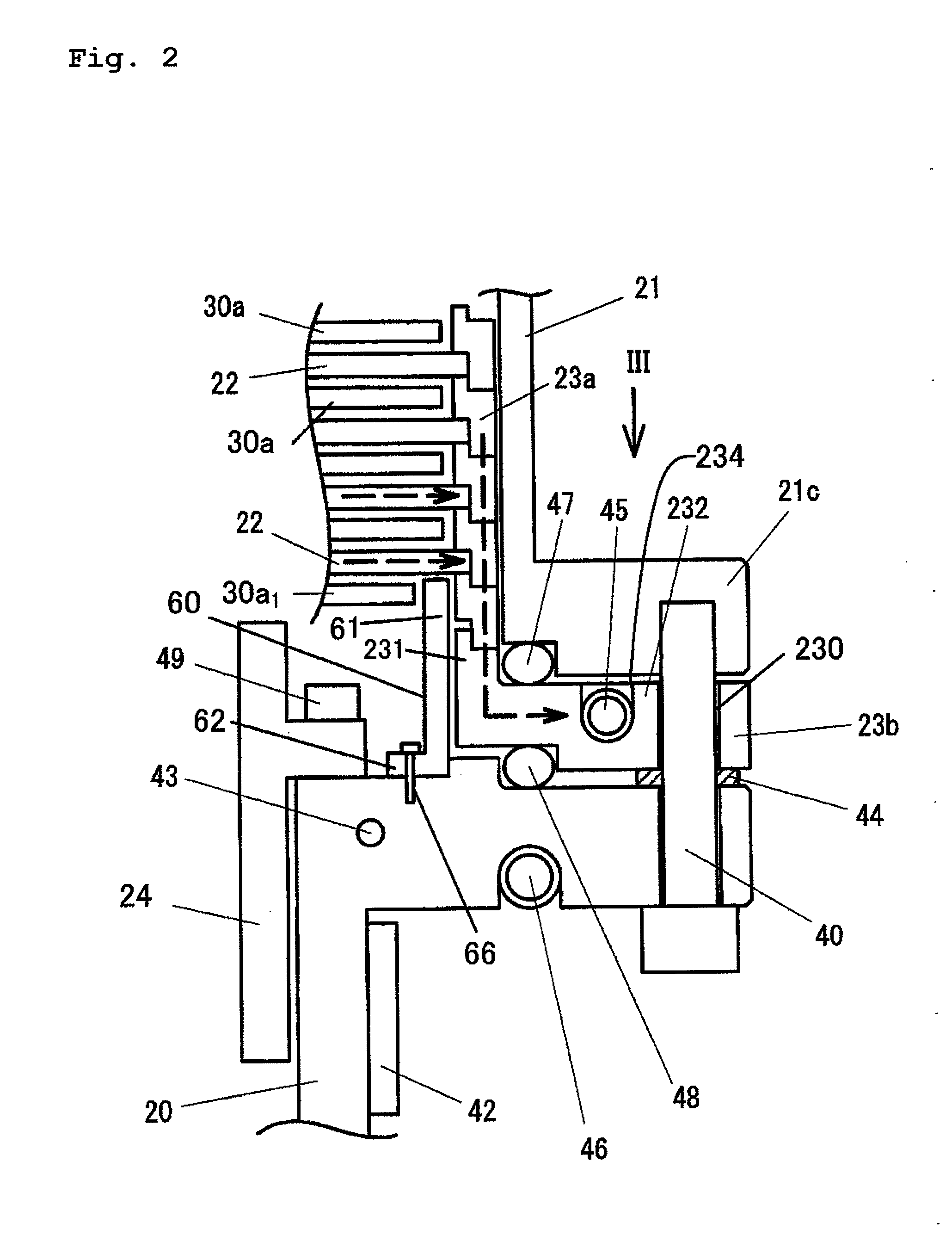
[0066]FIG. 5 is an enlarged view of an area in which a cooling spacer and an auxiliary ring are arranged as the second embodiment of the present invention.

[0067]The second embodiment illustrated in FIG. 5 differs from the first embodiment in the following structure.

[0068](a1) A cooling spacer 23c has a structure obtained by integrating the cooling spacer 23b illustrated in FIG. 2 and the bottom step spacer 23a arranged above the cooling spacer 23b with each other. In other words, the bottom step spacer 23a serves as the cooling spacer 23c.

[0069]In a turbo-molecular pump of the second embodiment, a plurality of spacers for positioning stationary blades 22 on a base 20 includes a plurality of spacers 23a and the cooling spacer 23c which bears the spacers 23a while supporting the bottom step stationary blade 22.

[0070](a2) A heat transfer ring 60A is integrally formed with the base 20. Therefore, in this structure, it is not necessary to manufacture a heat transfer ring as a separate m...

third embodiment

[0073]FIG. 6 is an enlarged view of an area in which a cooling spacer and an auxiliary ring are arranged as the third embodiment of the present invention. The third embodiment illustrated in FIG. 6 differs from the second embodiment in the following structure.

[0074](b1) A heat transfer ring 60B is integrally formed with a screw stator 24.

[0075]An attachment section of the screw stator 24, the attachment section being attached to a base 20, extends toward the outer peripheral side, and is bent upward on an end part thereof to form the heat transfer ring 60B. As with the first embodiment, the screw stator 24 is fixed to the base 20 with bolts 49. Accordingly, heat of the base 20 is transferred to the heat transfer ring 60B.

[0076]In a turbo-molecular pump of the third embodiment, a plurality of spacers for positioning stationary blades 22 on the base 20 includes a plurality of spacers 23a and a cooling spacer 23c which bears the spacers 23a while supporting the bottom step stationary b...


PUM


Abstract

A turbo-molecular pump comprises: a rotor having a plurality of stages of rotor blades and a cylindrical section; a plurality of stages of stationary blades alternately arranged with respect to the rotor blades; a stator arranged with a gap from the cylindrical section, the stator together with the cylindrical section constituting a screw groove pump section; a plurality of spacers stacked on a base, the spacers including at least one cooling spacer having a cooling section; a heater heating the stator; a temperature regulation section controlling the heater to regulate the temperature of the stator so as to be a reaction product accumulation prevention temperature; and an auxiliary ring for reaction product accumulation prevention at least a part of which is located in a space between the spacer facing a bottom step rotor blade, and the bottom step rotor blade.

Description

TECHNICAL FIELD[0001]The present invention relates to a turbo-molecular pump that is provided with a cooling passage for cooling a rotor having rotor blades and a temperature regulator.BACKGROUND ART[0002]Conventionally, in the process of dry etching, CVD, or the like in semiconductor manufacturing processes, processing is performed while supplying a large amount of gas in order to perform the process at high speed. Generally, a turbo-molecular pump that is provided with a turbine blade section and a screw groove pump section housed inside a pump case is used in the evacuation of a process chamber in the process of dry etching, CVD, or the like. When discharging a large amount of gas by the turbo-molecular pump, frictional heat generated in moving blades (rotor blades) is transmitted from the moving blades to stator blades (stationary blades), spacers, and a base in this order, and then released into cooling water in a cooling pipe provided in the base.[0003]However, when dischargin...

Claims


Application Information

Patent Timeline
Patent Type & Authority Applications(United States)
IPC IPC(8): F04D29/58F04D27/00F04D19/04
CPCF04D29/5806F04D27/006F04D19/042F04D27/02F04D29/584F04D29/5853
Inventor TSUTSUI, SHINGO
Owner SHIMADZU CORP
Why Eureka
Try Eureka