Coolant bypass for fuel cell stack

Inactive Publication Date: 2007-08-02
GM GLOBAL TECH OPERATIONS LLC
View PDF2 Cites 16 Cited by
  • Summary
  • Abstract
  • Description
  • Claims
  • Application Information

AI Technical Summary

Benefits of technology

[0008] According to another aspect of the invention, an electrochemical conversion assembly is disclosed. Particularly, the electrochemical conversion assembly can be a fuel cell, where even more particularly, it may be a PEM fuel cell. While it has been mentioned that one type of fuel cell that can benefit from the present invention is the PEM fuel cell, it will be appreciated by those skilled in the art that the use of other fuel cell configurations is also within the purview of the present invention. The electrochemical conversion assembly includes a plurality of anodes each configured to transport a first reactant, a plurality of cathodes each configured to transport a second reactant, and a membrane electrode assembly disposed between each of the anodes and cathodes such that together the anodes, cathodes and membranes define a stack. The assembly further includes a coolant system configured to regulate the temperature produced in the assembly by a reaction between the reactants. Features of the coolant system include a coolant inlet manifold and a coolant outlet manifold, the first configured to deliver at least a portion of a coolant between the anodes and cathodes, and the second configured to receive at least a portion of the coolant between the anodes and cathodes. The manifolds are in fluid communication with one another. The system also includes a coolant flowpath that allows coolant to flow in and around the stack. The coolant flowpath is broken up into a temperature-regulating flowpath and a bypass flowpath, where the first is configured to convey a first portion of the coolant through the stack such that the portion of coolant flowing past the stack elements (for example,

Problems solved by technology

Unfortunately, the presence of this coolant, which is essential to durability of the fuel cell during normal operating conditions, can inhibit proper fuel cell operation when the fuel cell system is cold, such as during start-up in an extremely cold environment For example, ambient temperatures during winter may be at or below minus 20 degrees Fahrenheit; by having the substantial entirety of available coolant flow pass through the fuel cell stack during such cold conditions, attainment of a preferred fuel cell operating temperature (which, for a PEM

Method used


Image

  • Coolant bypass for fuel cell stack
  • Coolant bypass for fuel cell stack
  • Coolant bypass for fuel cell stack

Examples


Embodiment Construction

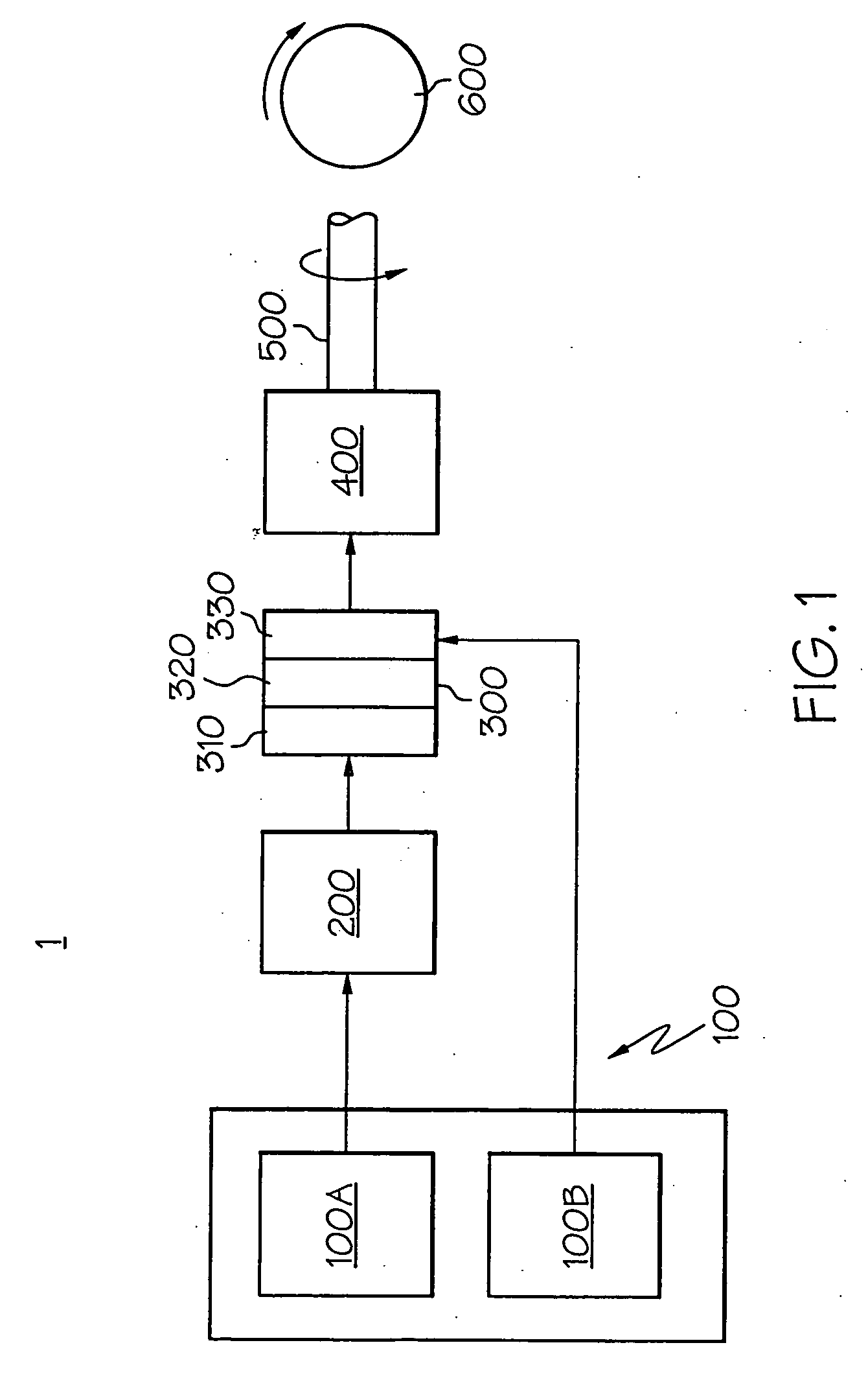
[0017] Referring initially to FIGS. 1 and 4, a block diagram highlights the major components of a mobile fuel cell system 1 according to the present invention, as well as a representative placement of a fuel cell system into an automotive application. Referring with particularity to FIG. 1, the system 1 includes a reactant delivery system 100 (made up of fuel source 100A and oxygen source 100B), fuel processing system 200, fuel cell 300, one or more energy storage devices 400, a drivetrain 500 and one or more motive devices 600, shown notionally as a wheel. While the present system 1 is shown for mobile (such as vehicular) applications, it will be appreciated by those skilled in the art that the use of the fuel cell 300 and its ancillary equipment is equally applicable to stationary applications. It will further be appreciated by those skilled in the art that the term “fuel cell”, while generally indicative of a single fuel cell within a larger stack of such cells, may also be used ...


PUM


Abstract

A heat regulating system for an electrochemical conversion assembly. In one embodiment, the electrochemical conversion assembly is a fuel cell, and the device includes one or more fluid-manipulating components to vary the amount of a coolant or related heat regulating fluid used to maintain a preferred temperature in the fuel cell. Preferred fuel cell operating temperatures can be more easily achieved by selectively bypassing a portion of the coolant around the fuel cell during certain temperature or power demand regimes. A controller can be used to monitor and selectively vary the extent to which at least one of these components modifies the flow of fluid past the fuel cell.

Description

BACKGROUND OF THE INVENTION [0001] The present invention relates generally to ways to selectively route coolant during operation of a fuel cell, and more particularly to bypassing at least a portion of the coolant around the fuel cell during cold start-up conditions. [0002] In many fuel cell systems, hydrogen or a hydrogen-rich gas is supplied through a flowpath to the anode side of a fuel cell while oxygen (such as in the form of atmospheric oxygen) is supplied through a separate flowpath to the cathode side of the fuel cell. An appropriate catalyst ionizes the two reactants such that the ionization and subsequent combination of the reactants produces electric current with heat and water vapor as reaction byproducts. In one form of fuel cell, called the proton exchange membrane (PEM) fuel cell, an electrolyte in the form of a membrane is sandwiched between two electrode plates that make up the anode and cathode. This layered structure of membrane sandwiched between two electrode pl...

Claims


Application Information

Patent Timeline
IPC IPC(8): H01M8/04
CPCH01M8/04029Y02E60/50H01M8/04089H01M8/04037
Inventor SIEPIERSKI, JAMES S.HOCH, MARTIN M.BEUTEL, MATTHEW J.WHITEHEAD, LEE C.
Owner GM GLOBAL TECH OPERATIONS LLC
Why Eureka
Try Eureka