Therapeutic Device

a technology of venous blood flow and therapeutic devices, applied in the field of therapeutic devices, can solve the problems of inability to function directional valves, damage, and distension of veins, and achieve the effect of enhancing venous blood flow through the limb

Inactive Publication Date: 2017-06-29
NEW TEC
View PDF21 Cites 12 Cited by
  • Summary
  • Abstract
  • Description
  • Claims
  • Application Information

AI Technical Summary

Benefits of technology

[0019]It is therefore an object of the present invention to provide an apparatus for enhancing venous blood flow through a limb of a subject that minimises or overcomes at least one of the disadvantages referred to above, or to provide the public with a useful or commercial choice.

Problems solved by technology

Small muscle groups move small amounts of blood during each contraction of the leg muscle and this is important as, since vein walls are thin and elastic, too much blood in a vein could cause the vein to distend, to suffer damage and to render the directional valves non-functional.
During long periods of muscular inactivity (e.g. when travelling on an aeroplane, car, bus or train, when confined to a wheelchair, or when bed ridden), the risk of a blood clot forming in a person increases as there may be little or no venous blood movement within the legs of the person.
In addition to stasis, with blood continuing to collect within the leg veins, the directional valves may leak, the veins may distend and suffer damage and hence release clotting factors which could also initiate clot formation.
However, although such sleeves may decrease the risk of a blood clot forming, the sleeves generally have the disadvantage that they do not decrease the risk to an acceptable level.
1. During compression of the sleeve, blood may be squeezed back into veins below the sleeve, thus increasing stasis in, and causing further distension of, the veins below the sleeve. This problem is exacerbated by long sleeve compression times, large compressed areas and if the veins located beneath the sleeve already contain too much blood.
2. Following compression, the sleeve is relaxed, and as the empty veins in the previously compressed muscle refill with blood from below the sleeve, there is no blood to push along the blood in the veins above the sleeve and thus the blood in the veins above the sleeve lies static until the sleeve is next compressed.
3. If there is any constriction of the veins above the sleeve, such as the veins located in a seated person's thighs, then the large volume of blood may distend and damage those veins.
To recapitulate, some of the known compression sleeves have disadvantages in that they can aggravate stasis below the sleeve during compression of the muscle, they cause stasis above the sleeve when the sleeve is relaxed, and may distend vein walls and render directional valves of the veins non-functional, thus increasing the risk of blood clot formation.
During the post-surgical period in hospital, patients are as a matter of course provided compression stockings and may be treated with usually large, cumbersome compression machines which employ compression sleeves which either cover the entire limb of the patient or act to compress a large region of the patient's body or limb.
The use of large, cumbersome compression machines in hospitals requires the immobilisation of the patient.
Typically, the compression machines and sleeves are designed to operate only whilst the patient is in bed and attached to the compression machine and such machines and sleeves are large, cumbersome devices that do not permit patient ambulation.
This leads to a decrease in patient compliance whilst in hospital, as they are required to remove the compression sleeves to move around and during the post-hospital admittance period during which time they will not be subjected to compression prophylaxis due to the unavailability of compression machines (which are large, cumbersome and costly) during the period of greatest risk of DVT whilst the patient recovers at home.
Similarly, known compression devices are not configured in such a manner that they are adaptable to use on transportation conveyances such as airplanes, trains, and other motor vehicles.
This increases the risk of developing a DVT amongst susceptible populations.
Compression machines and sleeves currently in use also suffer from the disadvantage of uneconomical design and configuration in so far as they incorporate compression means which are unwieldy, unnecessarily complicated, not aesthetically pleasing and require the use of multiple tubes connected to a pump for inflating the compressors of the compression sleeve or sleeves.
This makes apparatus currently known and in use cumbersome.

Method used


Image

  • Therapeutic Device
  • Therapeutic Device
  • Therapeutic Device

Examples


Embodiment Construction

[0104]In the figures, like reference numerals refer to like features.

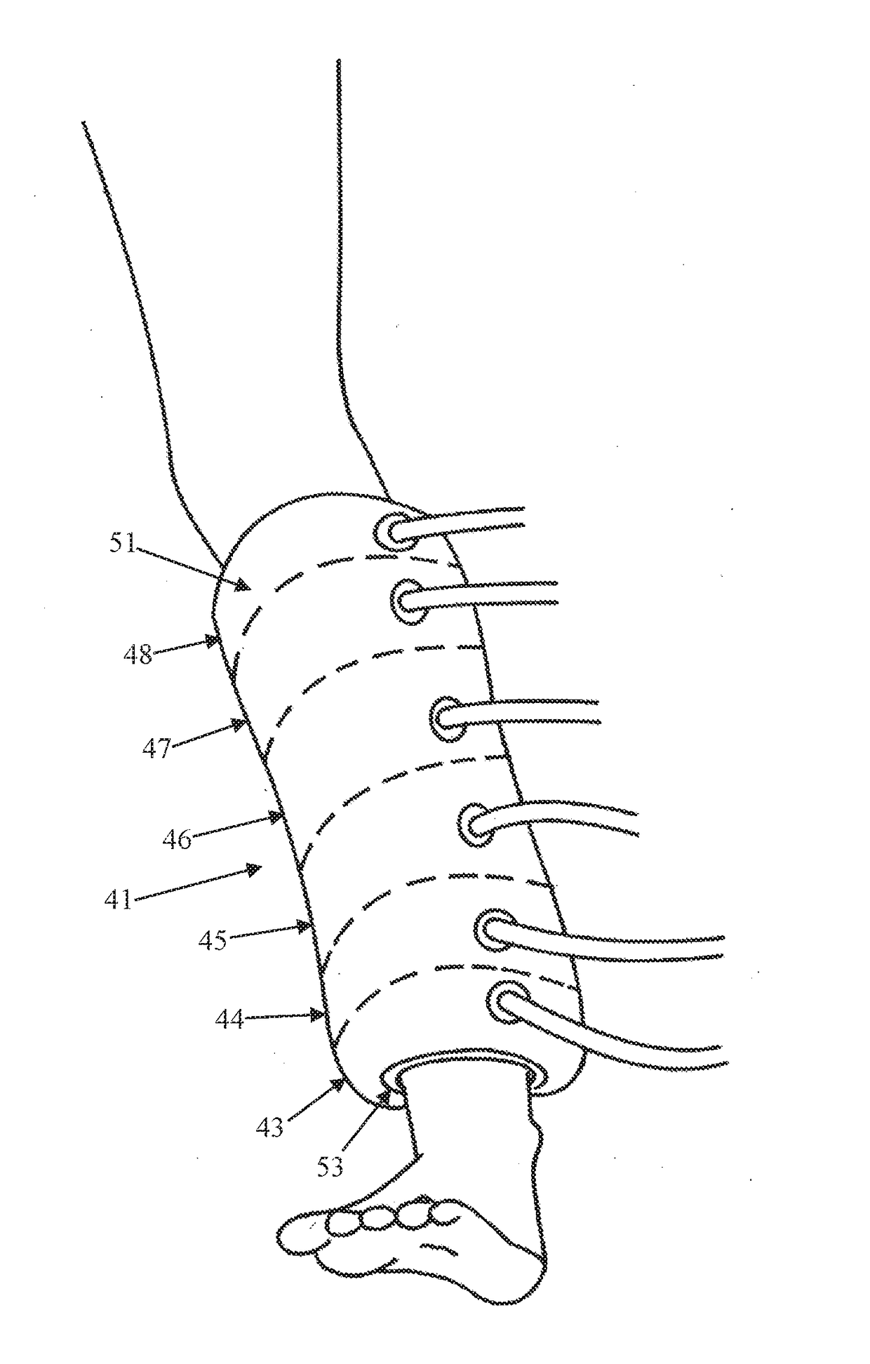
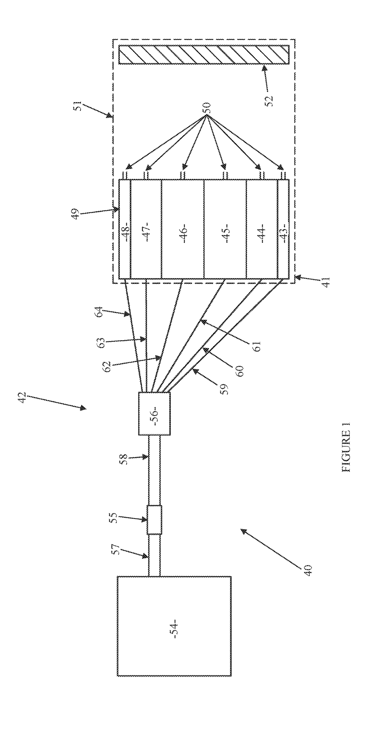
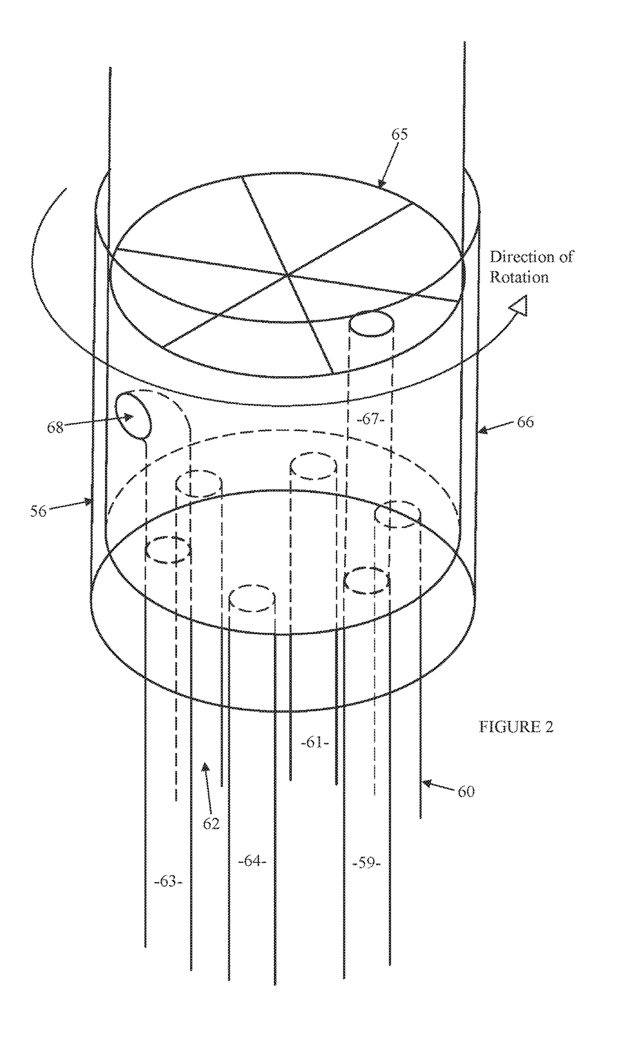
[0105]FIG. 1 shows an apparatus 40 for enhancing venous blood flow through a lower leg of a person. The apparatus 40 includes an inflatable compression sleeve 41 (best seen in FIG. 4) extendable around the person's leg and an air delivery system 42 for delivering air to the compression sleeve 41. The compression sleeve 41 is similar to a sphygmomanometer.

[0106]The compression sleeve 41 has six inflatable chambers 43-48 situated next to one another along the compression sleeve 41. The chambers 43-48 are elongate and extend around the limb, as seen in FIG. 4. The chambers 43-48 are provided by a sealed rubber bladder 49. Chambers 43 and 48 are narrower than chambers 44-47 and hold less air. (Chambers 43 and 48, however, need not be narrower than chambers 44-47). Each chamber 43-48 has a pressure relief valve 50 that opens when chamber 43-48 pressure exceeds about 35 mm Hg. The pressure relief valves 50 prevent the ch...


PUM


Abstract

An apparatus 40 for enhancing venous blood flow through a limb of a subject includes a detachable compression sleeve 41 extendable around the subject's limb and having a plurality of compressors 43-48 situated next to one another along the sleeve 41. In use, the compressors 43-48 substantially encircle the limb and compress the limb in a continuous cyclical compression sequence to move blood within the limb from the distal end of the sleeve 41 to the proximal end to replicate venous blood flow and to prevent backflow. In particular, as a said first compressor begins to compress the limb, a said second compressor preceding the first compressor in sequence already compresses the limb and continues to compress the limb at least until the first compressor compresses the limb to substantially the same extent as the second compressor, and a said third compressor which precedes the second compressor in sequence ceases to compress the limb.

Description

TECHNICAL FIELD[0001]This invention relates to an apparatus for enhancing venous blood flow through a limb of a subject. In particular, the invention concerns an apparatus for preventing deep vein thrombosis.BACKGROUND ART[0002]Deep vein thrombosis (DVT) is characterised by the development of a clot within a deep vein anywhere in the body but almost exclusively in the veins of the calf or thigh. DVTs are a large source of morbidity, the most common serious complication of DVT being a pulmonary embolism whereby a blood clot breaks free from a vein wall, travels to a lung and blocks an artery.[0003]The following factors can promote blood clot formation within a vein:[0004]1. Increased coagulation of the blood (e.g. women on hormones);[0005]2. Increased clotting factors in the blood;[0006]3. Damage to a vein wall (e.g. trauma to a leg), whereby coagulation factors are released and a chemical cascade causes a clot to form; and[0007]4. Stasis of the blood, as happens in dependant limbs w...

Claims


Application Information

Patent Timeline
Patent Type & Authority Applications(United States)
IPC IPC(8): A61H9/00A61H1/00
CPCA61H9/0078A61H1/008A61H2201/50A61H2205/10A61H2209/00A61H9/0092A61H2011/005A61H2201/1207A61H2201/5097A61H2201/0192A61H2201/1472A61H2201/5071A61H2201/5053A61H2201/5056A61H11/00
Inventor WREN, GREGORY ALLANMEYER, WALTERBENNETT, WAYNE
Owner NEW TEC
Why Eureka
Try Eureka