
Engine control device

a control device and engine technology, applied in the direction of electric control, speed sensing governors, machines/engines, etc., can solve the problems of negative effect and acceleration performance drop, and achieve the effects of reducing vibration, maintaining acceleration performance, and limited engine torqu

Active Publication Date: 2017-06-29
MAZDA MOTOR CORP
View PDF3 Cites 2 Cited by
  • Summary
  • Abstract
  • Description
  • Claims
  • Application Information

AI Technical Summary

Benefits of technology

The present invention is an engine control device that can limit the increase in engine torque to suppress the rolling movement of the power train during low-speed driving. This can reduce vibration caused by the rolling movement and maintain the acceleration performance of the vehicle. The device can accurately determine the condition of the rolling movement to start or terminate the control for suppressing the rolling movement. Additionally, the device can effectively prevent the power train from being pushed backward by the reaction force of the drive shaft. Overall, the engine control device can appropriately suppress vibration caused by the rolling movement of a power train while maintaining the acceleration performance of the vehicle.

Problems solved by technology

However, if the engine torque is increased slowly, vibration at the time of acceleration may be suppressed but there is a negative effect that acceleration performance comes down.

Method used


Image

  • Engine control device
  • Engine control device
  • Engine control device

Examples


Embodiment Construction

[0035]With reference to the accompanying drawings, an engine control device according to one embodiment of the present invention will now be described.

[System Configuration]

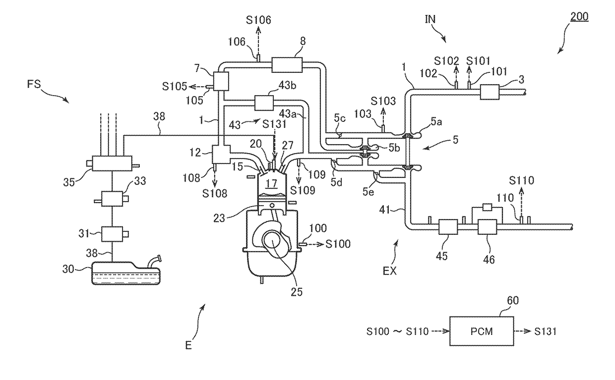
[0036]First of all, with reference to FIG. 1, an engine system to which an engine control device according to one embodiment of the present invention is applied is described. FIG. 1 is a schematic configuration diagram of an engine system to which an engine control device according to one embodiment of the present invention is applied.

[0037]As shown in FIG. 1, an engine system 200, mainly, comprises an engine E such as a diesel engine, an air intake system IN for supplying intake air to the engine E, a fuel supply system FS for supplying fuel to the engine E, an exhaust gas system EX for discharging exhaust gas of the engine E, sensors 96 to 110 for detecting various parameters related to the engine system 200, and a PCM (Power-train Control Module) 60 for performing control of the engine system 200. The engine s...


PUM


Abstract

A PCM (60) as an engine control device comprises a torque controlling unit (65) configured to control an engine torque based on an accelerator actuated amount. The torque controlling unit (65) is configured, after an accelerator actuated amount is started to increase, and when a rolling movement is being produced in a power train (PT) which includes at least an engine fixed to a vehicle body by an engine mount, to control for limiting increase in the engine torque so as to make an actual increase rate of the engine torque smaller than a nominal increase rate of the engine torque according to an increase in the accelerator actuated amount, in order to suppress the rolling movement.

Description

BACKGROUND OF THE INVENTION[0001]Field of the Invention[0002]The present invention relates to an engine control device, and more particularly to an engine control device for controlling engine torque based on an accelerator actuated amount or the like.[0003]Description of Related Art[0004]When a vehicle is to be accelerated (especially when a vehicle movement is changed from a deceleration mode to an acceleration mode), vibration may occur in the vehicle if engine torque is increased abruptly, so that a control has conventionally been adopted to have the engine torque increased slowly for suppressing such possible vibration. However, if the engine torque is increased slowly, vibration at the time of acceleration may be suppressed but there is a negative effect that acceleration performance comes down. A technique for solving such a problem is disclosed in Patent Document 1 (Japanese Laid-Open Patent Publication 2005-155412 A), for example.[0005]The Patent Document 1 discloses a tech...

Claims


Application Information

Patent Timeline
Patent Type & Authority Applications(United States)
IPC IPC(8): F02D41/10F16H63/50G01P3/44F02D31/00
CPCF02D41/10F02D31/001F02D2200/101G01P3/44F02D2200/602F16H63/50F02D41/00F02D2200/10F16H59/70F02D2200/1012F02D2250/14F02D2250/26F02D2250/28
Inventor KONOMI, KENJIROUJIHARA, KENKO
Owner MAZDA MOTOR CORP
Learn More