
Oil separator

Active Publication Date: 2017-06-29
SAMSUNG ELECTRONICS CO LTD
View PDF12 Cites 2 Cited by
  • Summary
  • Abstract
  • Description
  • Claims
  • Application Information

AI Technical Summary

Benefits of technology

The patent describes a refrigeration system that separates oil from refrigerant before it is discharged. The system includes a long refrigerant discharge pipe that extends to the bottom of the container to prevent oil from being discharged first. The separated oil flows down through an oil passage hole and is further prevented from scattering. The technical effect of this system is improved oil separation and reduction of oil scattering, which results in improved refrigeration efficiency.

Problems solved by technology

However, the present inventors have discovered that the above-described configuration of the oil separator does not sufficiently solve the object of improving the separation efficiency of the oil.
However, when downsizing the oil separator, with the configuration of the above-described conventional oil separator, there is a problem that oil is not sufficiently separated from the refrigerant.
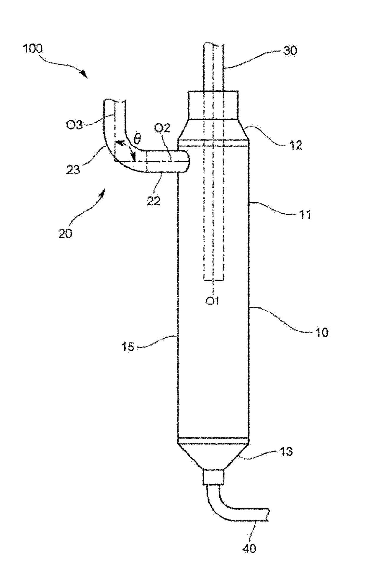
If the inner diameter of the inlet pipe is more than 0.44 times the inner diameter of the container, the inlet pipe is so close to the center of the container so that turning of the oil-containing refrigerant is difficult and the separation efficiency is reduced.
With this configuration, even if the oil received in the lower tapered portion is scattered, since the discharge port is provided above the lower tapered portion, it may be difficult that the scattered oil flows into the discharge port.
Because of this, the oil may be prevented from being introduced in the upward direction into the inside of the container, and the oil may be difficult to stay in the upper side of the inlet pipe.

Method used


Image

  • Oil separator
  • Oil separator
  • Oil separator

Examples


Embodiment Construction

[0053]Hereinafter, certain exemplary embodiments of the present disclosure will be described in detail with reference to the accompanying drawings.

[0054]The matters defined herein, such as a detailed construction and elements thereof, are provided to assist in a comprehensive understanding of this description. Thus, it is apparent that exemplary embodiments may be carried out without those defined matters. Also, well-known functions or constructions are omitted to provide a clear and concise description of exemplary embodiments. Further, dimensions of various elements in the accompanying drawings may be arbitrarily increased or decreased for assisting in a comprehensive understanding.

[0055]The terms “first”, “second”, etc. may be used to describe diverse components, but the components are not limited by the terms. The terms are only used to distinguish one component from the others.

[0056]The terms used in the present application are only used to describe the exemplary embodiments, b...


PUM


Abstract

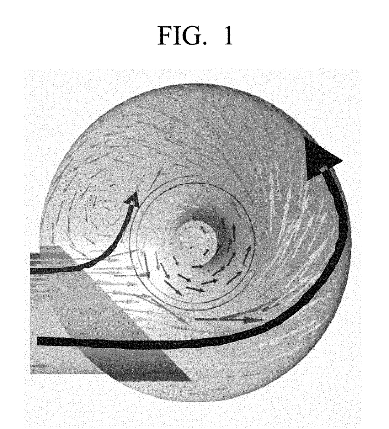
An oil separator includes a container having an inner circumferential surface of a cylindrical shape; an inlet pipe that penetrates through from an outside of the container to an inside of the container, comprises an inlet port through which the oil-containing refrigerant is introduced to the container; and a refrigerant discharge pipe that is provided coaxially with a central axis of the container in a top of the container, projects from the top of the container toward a bottom of the container, and comprises a discharge port which is disposed below the inlet port and allows oil removed refrigerant to be discharged. The oil-containing refrigerant flowing out of the inlet port of the inlet pipe is not branched by the refrigerant discharge pipe, and forms a single flow flowing in one direction along an outer circumferential surface of the refrigerant discharge pipe and the inner circumferential surface of the container.

Description

CROSS-REFERENCE TO RELATED APPLICATIONS[0001]This application claims benefit of foreign priority from Japanese Patent Application No. 2015-254229 filed Dec. 25, 2015 in the Japan Patent Office, and claims priority from Korean Patent Application No. 10-2016-0021486 filed Feb. 23, 2016 in the Korean Intellectual Property Office, the disclosures of both of which are incorporated herein by reference in their entireties.BACKGROUND[0002]1. Field[0003]The present disclosure relates to an oil separator to separate oil from refrigerant discharged from a compressor of a refrigerant circuit.[0004]2. Related Art[0005]An example of an oil separator used in a refrigerant circuit includes a container having a cylindrical shape, an inlet pipe that is disposed to penetrate through a side wall of the container and introduces refrigerant containing oil to turn along an inner circumferential surface of the container, and a refrigerant discharge pipe that is disposed to penetrate through a top wall of t...

Claims


Application Information

Patent Timeline
IPC IPC(8): F25B43/02F25B13/00
CPCF25B13/00F25B43/02F25B2500/01
Inventor KUROKAWA, TAKAMITSUTAKEICHI, HISASHIEGUCHI, HIROAKI
Owner SAMSUNG ELECTRONICS CO LTD
Learn More