Back plate and liquid crystal display device having the same

a liquid crystal display and back plate technology, applied in the field of liquid crystal display, can solve the problems of increasing the cost of back plates, disadvantageous to the lightening and thinning reducing the cost of the entire device, so as to achieve the effect of reducing the cost, reducing the thickness, and reducing the cost of the entire lcd devi

Active Publication Date: 2017-06-29
TCL CHINA STAR OPTOELECTRONICS TECH CO LTD
View PDF2 Cites 0 Cited by
  • Summary
  • Abstract
  • Description
  • Claims
  • Application Information

AI Technical Summary

Benefits of technology

[0004]Due to the disadvantages existing in the related art, the present disclosure provides a back plate of a LCD device having a smaller thickness and being able to satisfy its rigidity requirement, which is helpful for the lightening and thinning of the entire LCD device and cost reduction.
[0015]In comparison with the related art, embodiments of the present disclosure provide a back plate of a LCD device, wherein a plurality of first reinforcing ribs and a plurality of second reinforcing ribs crossing each other are disposed in a first region as an appearance of the entire LCD device and have crossing parts in a “” shape, “T” shape or “L” shape therebetween, so that the back plate has a smaller thickness and can satisfy its rigidity requirement, thereby being helpful for the lightening and thinning of the entire LCD device and cost reduction.

Problems solved by technology

The back plate having a larger thickness not only increases the cost, but also is disadvantageous to the lightening and thinning of the entire device.

Method used


Image

  • Back plate and liquid crystal display device having the same
  • Back plate and liquid crystal display device having the same
  • Back plate and liquid crystal display device having the same

Examples


embodiment 1

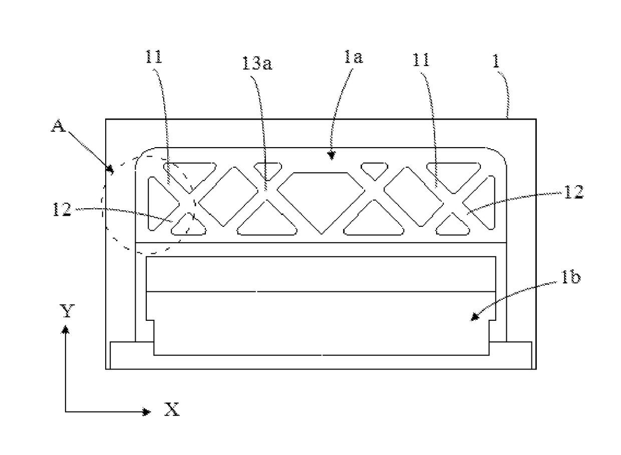
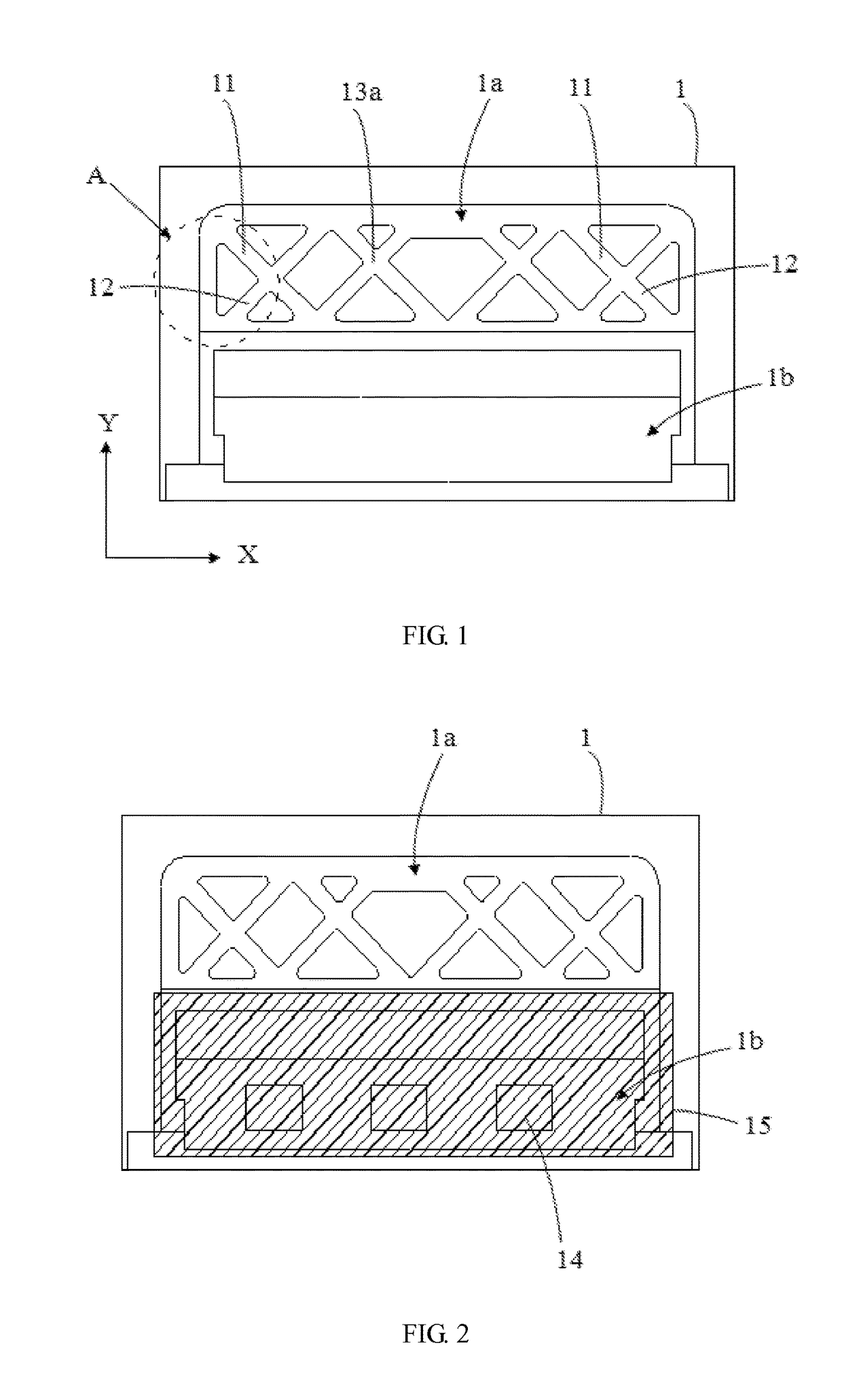
[0023]Referring to FIGS. 1-3, the present embodiment provides a back plate of a LCD device, wherein the back plate 1 is mainly applied to an integrated LCD device, and includes a first region 1a and a second region 1b. As illustrated in FIG. 2, the second region 1b is used to accommodate circuit elements 14 with a cover 15 for covering the circuit elements 14 connected thereon, wherein the first region 1a and the cover 15 together form an appearance of a back surface of the LCD device.

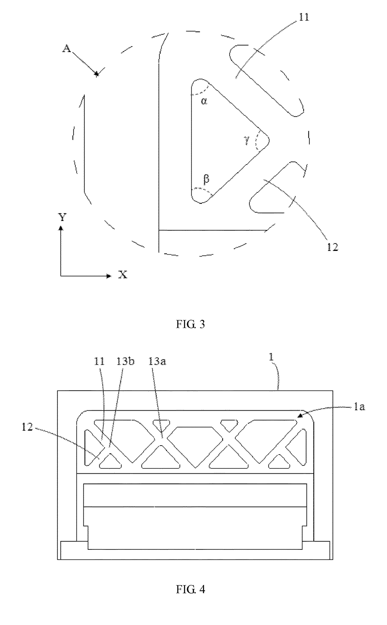
[0024]As illustrated in FIGS. 1 and 2, a plurality of first reinforcing ribs 11 and a plurality of second reinforcing ribs 12 crossing each other are disposed in the first region 1a. The plurality of first reinforcing ribs 11 are arranged to be spaced apart from each other in a horizontal direction (X direction as shown in the figures), and an angle α between the first reinforcing rib 11 and a vertical direction (Y direction as shown in the figures) may be selected to be 40° to 50°. The plurality of se...

embodiment 2

[0028]The present embodiment differs from embodiment 1 in that: as illustrated in FIG. 4, in the first region 1a of the back plate 1, among the crossing parts between the first reinforcing ribs 11 and the second reinforcing ribs 12, some crossing parts 13a are of the “” shape as described in embodiment 1, while other crossing parts 13b are of a “T” shape.

[0029]Regarding the “T” shaped crossing, if taking the crossing part 13b as a central point, the first reinforcing rib 11 extends toward both ends from the crossing part 13b, while the second reinforcing rib 12 extends toward only one end from the crossing part 13b; or, the second reinforcing rib 12 extends toward both ends from the crossing part 13b, while the first reinforcing rib 11 extends toward only one end from the crossing part 13b; and at this time, the first reinforcing ribs 11 and the second reinforcing ribs 12 are perpendicular to each other. In addition, if the values of the angles are selected such that the first and s...

embodiment 3

[0031]The present embodiment differs from embodiment 1 in that: as illustrated in FIG. 5, in the first region 1a of the back plate 1, among the crossing parts between the first reinforcing ribs 11 and the second reinforcing ribs 12, some crossing parts 13a are of the “” shape as described in embodiment 1, while other crossing parts 13c are of a “L” shape.

[0032]Regarding the “L” shaped crossing, if taking the crossing part 13c as a central point, the first reinforcing rib 11 and the second reinforcing rib 12 extend toward only one end from the crossing part 13c respectively, and at this time, the first reinforcing ribs 11 and the second reinforcing ribs 12 are perpendicular to each other. In addition, if the values of the angles are selected such that the first and second reinforcing ribs 11 and 12 are not perpendicular to each other, the crossing part 13c between the first reinforcing rib 11 and the second reinforcing rib 12 is defined to be approximate to the “L” shape.

[0033]In con...


PUM

PropertyMeasurementUnit
angleaaaaaaaaaa
angleaaaaaaaaaa
γaaaaaaaaaa

Abstract

A back plate of a liquid crystal display (LCD) device includes a first region as an appearance of the entire LCD device, in which a plurality of first and second reinforcing ribs crossing each other are disposed, the plurality of first reinforcing ribs are arranged to be spaced apart from each other in a horizontal direction, and an angle α between the first reinforcing rib and a vertical direction ranges from 40° to 50°. The plurality of second reinforcing ribs are arranged to be spaced apart from each other in the horizontal direction, and an angle β between the second reinforcing rib and the vertical direction ranges from 40° to 50°. Each of the first reinforcing ribs at least crosses one of the second reinforcing ribs. A liquid crystal display device including the back plate as described above is also disclosed.

Description

TECHNICAL FIELD[0001]The present disclosure relates to the liquid crystal display technical field, and in particular, to a back plate of a liquid crystal display device and a liquid crystal display device having the same.BACKGROUND ART[0002]With the evolution of photoelectric and semiconductor technologies, the flourishing development of a flat panel display is driven, and in various flat panel displays, liquid crystal displays (LCDs) have become the mainstream of the market because of having various superior characteristics, such as high space utilization, low power consumption, no radiation and low electromagnetic interference or the like. Generally, a LCD device includes a back frame, a back light module (BLM), a liquid crystal panel and a front frame, wherein the back frame and the front frame are fixedly coupled to form an accommodating space, and the BLM and the liquid crystal panel are disposed opposite to each other and accommodated in the accommodating space. Furthermore, t...

Claims


Application Information

Patent Timeline
Patent Type & Authority Applications(United States)
IPC IPC(8): G02F1/1333F21V8/00
CPCG02F1/133308G02B6/0093G02F2201/54G02F2001/133302G02F2001/133314G02F1/133314G02F1/133302
Inventor LV, CHENGLING
Owner TCL CHINA STAR OPTOELECTRONICS TECH CO LTD
Why Eureka
Try Eureka