Corrugated Bridging Member

a bridging member and corrugated technology, applied in the direction of rod connections, walls, mechanical equipment, etc., can solve the problems of reducing the service life of the bridging member

Active Publication Date: 2017-07-06
SIMPSON STRONG TIE
View PDF0 Cites 17 Cited by
  • Summary
  • Abstract
  • Description
  • Claims
  • Application Information

AI Technical Summary

Benefits of technology

[0008]The present invention provides a bridging member with mounting sections having notches that interlock with the central web of a wall stud to provide torsional rigidity. The notches are braced by the body of the bridging member, allowing the notches to resist substantially high loads.
[0013]The present invention employs a bridging connector with longitudinally-offset notches that create a tighter interface with the central web of the wall stud and therefore result in improved performance in the connection.
[0015]In one embodiment of the present invention, the notches of the mounting section are formed with a shape that makes for a stronger die punch that will last longer. The inner edges of the first and second body parts are formed with sections having a curved arc such that the punch can be larger and is thus stronger. The inner edges of the first and second bodies of the notches can also be shaped so that one of the first and second inner edges flares outwardly as it nears the outer end of the notch. This feature makes it easier to engage the notches with the central web of the stud.
[0018]The interlocking connection between the bridging members and the wall studs allow the bridging members to be firmly connected to the wall studs without the use of fasteners.

Problems solved by technology

Steel studs have excellent columnar strength when they are straight, but a significant portion of that strength is lost if the studs are twisted.
When metal studs twist or bend, they lose their weight-bearing capacity, multiplying the damage caused directly by fire.

Method used


Image

  • Corrugated Bridging Member
  • Corrugated Bridging Member
  • Corrugated Bridging Member

Examples


Embodiment Construction

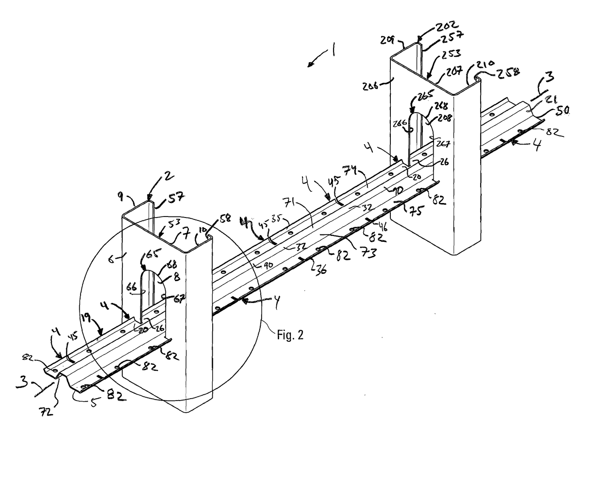
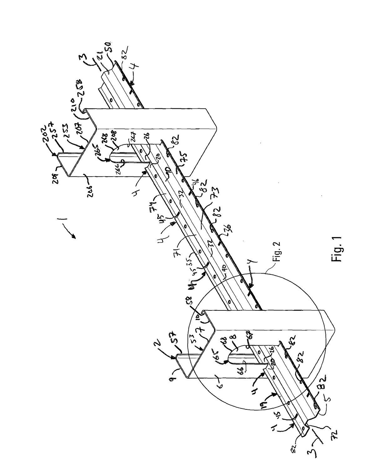
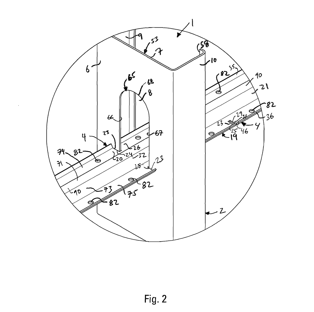
[0039]As shown in FIGS. 1 and 8, the present invention is a building connection 1 that comprises a plurality of substantially vertical wall studs 2 and 202 and one or more substantially horizontal, interconnected bridging members 19 and 219. The wall studs 2 and 202 are typically one of several sequentially-arranged, cold-formed steel studs 2 and 202 in the frame of a building wall. The bridging members 19 and 219 are separate, preferably cold-formed galvanized steel members that interface with the plurality of wall studs 2 and 202. The first and second bridging members 19 and 219 each have a longitudinal, central axis 3 and 203 that are preferably in alignment. Each bridging member 19 and 219 has a plurality of mounting sections 4 and 204 and opposed first and second end sections 5 and 25, and 205 and 225 at the ends of the bridging members 19 and 219.

[0040]FIG. 8 shows a first bridging member 19 and a second bridging member 219. Preferably, the first and second bridging members 19...


PUM


Abstract

A building connection between a plurality of vertical wall studs made with one or more bridging members to brace the wall studs. The one or more bridging members are formed with mounting sections that are received in openings of the wall studs and the mounting sections are bracketed by end sections where bridging members can overlap. The bridging members interface with the web of the wall studs to brace them.

Description

BACKGROUND OF THE INVENTION[0001]The present invention relates to steel stud building wall systems and especially to an apparatus for stabilizing steel studs to prevent lateral movement and torsion in such systems.[0002]Many buildings are constructed with steel stud wall framing. When a wall is built with any kind of stud, wood or steel, it is generally desirable to fix sequential studs relative to each other against lateral movement and torsion. In steel-stud walls, an elongated steel bridging member is typically inserted horizontally through pre-punched openings in a series of vertical studs for this purpose. Steel studs have excellent columnar strength when they are straight, but a significant portion of that strength is lost if the studs are twisted. Because steel studs are particularly vulnerable to torsion, the bridging members, which are typically channel-shaped and have a horizontal web and two vertical side flanges, are made to closely fit the openings in the vertical studs...

Claims


Application Information

Patent Timeline
Patent Type & Authority Applications(United States)
IPC IPC(8): E04B1/41E04B2/58
CPCE04B1/40E04B2103/06E04B2/58E04B2/763F16B7/0473Y10T403/50
Inventor DAUDET, LARRY RANDALL
Owner SIMPSON STRONG TIE
Why Eureka
Try Eureka