
Static bilge pump

a bilge pump and bilge technology, applied in the direction of machines/engines, vessels, transportation and packaging, etc., can solve the problems of pump, bulky devices on the exterior of the hull, water collecting in the bilge, etc., and achieve the effect of easy integration with the existing hull

Inactive Publication Date: 2017-07-06
PALMISANO DOUG
View PDF20 Cites 3 Cited by
  • Summary
  • Abstract
  • Description
  • Claims
  • Application Information

AI Technical Summary

Benefits of technology

The present invention provides a static bilge pump that does not have any moving parts and is easy to install in existing boat hulls. This helps to improve the efficiency and reliability of the pump.

Problems solved by technology

Since boats were first built, water collecting in the bilge, or the bottom of the interior of the hull, has been a problem.
However, because even when a boat is at rest, it is still subject to wind, current and other forces, such automatic drains often do not remain completely closed while a boat is at rest.
Another difficulty encountered with automatic drains is that they typically include components exterior to the hull.
Pumps, which include bulky devices on the exterior of the hull are thus not desirable.
Because many boats are subjected to harsh conditions, it is not unusual for a bilge pump to become damaged or to cease functioning.
Bilge pumps may require maintenance and may be inefficient.
These substances often wear out when subjected to salt water.
This further complicates maintenance of the system's.

Method used


Image

  • Static bilge pump
  • Static bilge pump
  • Static bilge pump

Examples


Embodiment Construction

[0053]Before explaining at least one embodiment of the invention in detail, it is to be understood that the invention is not limited in its application to the details of construction and to the arrangements of the components set forth in the following description or illustrated in the drawings. The invention is capable of other embodiments and of being practiced and carried out in various ways. Also, it is to be understood that the phraseology and terminology employed herein are for the purpose of description and should not be regarded as limiting.

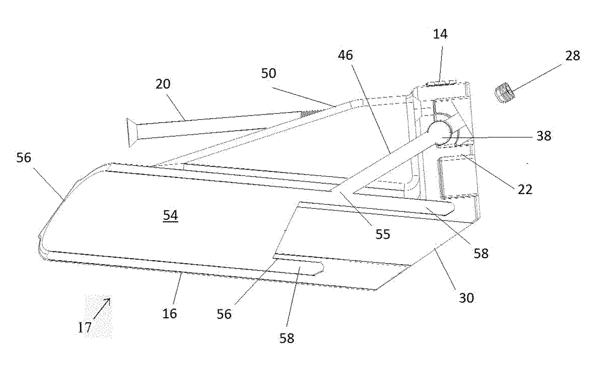
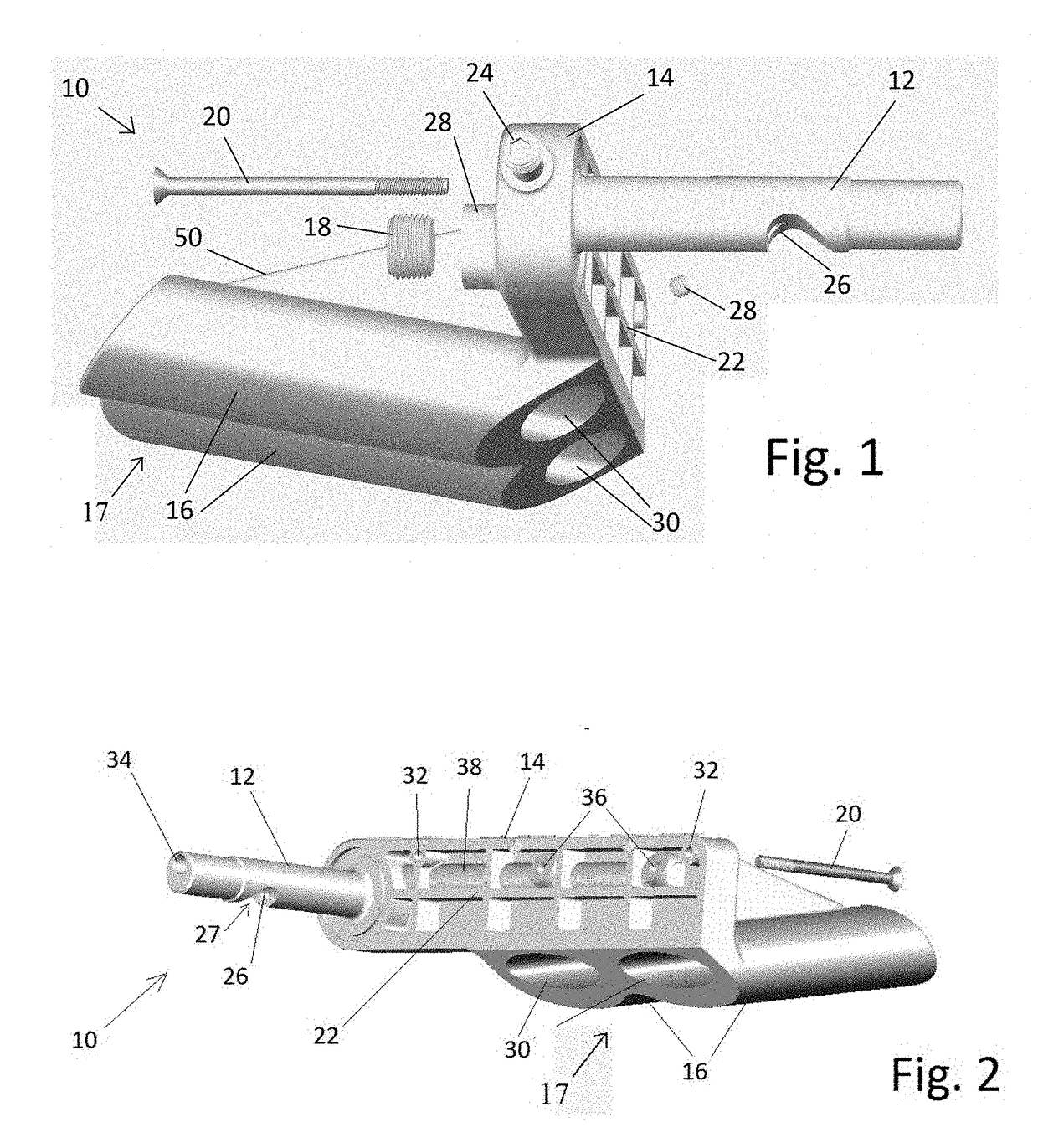
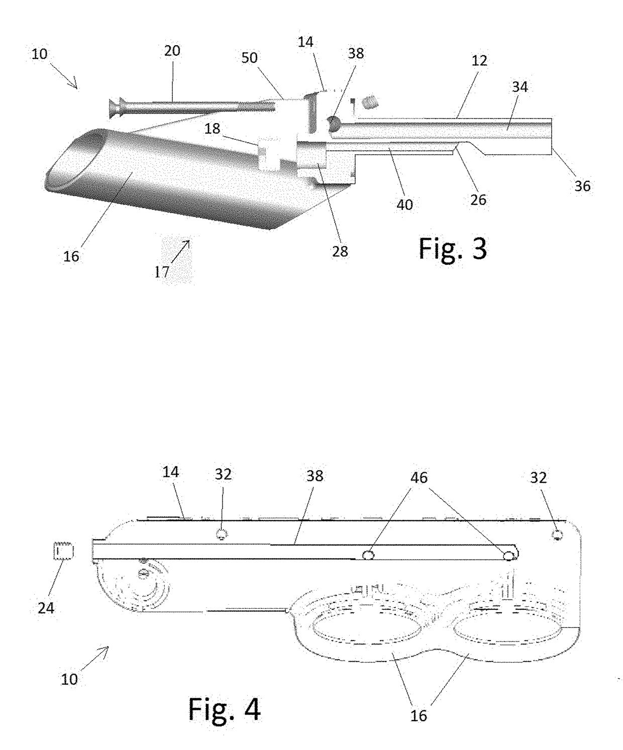
[0054]Disclosed is a static bilge pump for watercraft requiring no moving parts. The static bilge pump may be attached to the hull over the drain hole commonly found at the back of the boat adjacent to the lowest point of the bilge. The static bilge pump may remove water from the bilge of a boat. When the boat is not submerged, the boat's original drain may still be utilized.

[0055]In the following description, the term “distal” generally r...


PUM


Abstract

A static bilge pump has a body surrounded by a shell, forming a motive plenum therebetween. Inlets in the front of the shell allow a motive fluid to enter the motive plenum. The motive plenum tapers, decreasing in cross-sectional area along with width as it moves toward its aft, and ends at a motive nozzle. The body houses a suction chamber in fluid communication with a suction inlet that is in fluid communication with the bilge of a boat. Ejectors are positioned proximal to and between the motive nozzle and the discharge outlet. When the static bilge pump is exposed to fluid flow from its front to its stern, such as when a boat is in motion, water enters the motive inlets, filling the motive Plenum and acting as a motive fluid. The motive fluid is ejected at high pressure from the motive nozzle, creating suction at the ejectors and discharging the motive fluid as well as liquid with in the suction chamber out the discharge outlet.

Description

CROSS-REFERENCE TO RELATED APPLICATIONS[0001]This application is a continuation-in-part of U.S. patent application Ser. No. 14 / 316,730 filed on Jun. 26, 2014, which issued on Mar. 21, 2017 as U.S. Pat. No. 9,598,146. This application claims priority to U.S. Provisional Application Ser. No. 61 / 839,847 filed on Jun. 26, 2013, the contents of which are hereby incorporated in their entirety.STATEMENT REGARDING FEDERALLY SPONSORED RESEARCH OR DEVELOPMENT[0002]Not Applicable.NAMES OF PARTIES TO A JOINT RESEARCH AGREEMENT[0003]Not ApplicableREFERENCE TO SEQUENCE LISTING, A TABLE, OR A COMPUTER PROGRAM LISTING APPENDIX SUBMITTED ON A COMPACT DISC AND INCORPORATION-BY-REFERENCE OF THE MATERIAL[0004]Not Applicable.BACKGROUND OF THE INVENTION[0005]Field of Endeavor[0006]The present invention relates to systems and devices for draining the bilge of a vessel in a body of water. More particularly, the invention relates to systems and devices having no moving parts and which may be used to drain a...

Claims


Application Information

Patent Timeline
Patent Type & Authority Applications(United States)
IPC IPC(8): F04F5/46F04F5/10B63B13/00
CPCF04F5/46F04F5/10B63B13/00F04F1/06F04F1/10F04F1/18
Inventor PALMISANO, DOUG
Owner PALMISANO DOUG
Learn More