
Pointer driving motor unit and control method of pointer driving motor unit

a technology of pointer driving and control method, which is applied in the direction of electric winding, instruments, and horology, can solve the problems of reducing the size of the time display module and limiting the size of the main control portion, so as to reduce the size of the unit and ensure controllability

Inactive Publication Date: 2017-07-06
SEIKO INSTR INC
View PDF8 Cites 2 Cited by
  • Summary
  • Abstract
  • Description
  • Claims
  • Application Information

AI Technical Summary

Benefits of technology

The invention allows for reducing the size of units and ensuring control over multiple units at the same time.

Problems solved by technology

However, in the technology described in JP-A-2002-323577, it was often difficult for the time display module to reduce the size thereof.
In addition, in the main control portion in the unitized module, when the number of additional modules increases or the functions of each module are improved, a case where it is not possible to respond thereto due to a processing load or the restriction of the size in the main control portion may occur.

Method used


Image

  • Pointer driving motor unit and control method of pointer driving motor unit
  • Pointer driving motor unit and control method of pointer driving motor unit
  • Pointer driving motor unit and control method of pointer driving motor unit

Examples


Embodiment Construction

[0025]Hereinafter, an embodiment of the invention will be described with reference to the drawings.

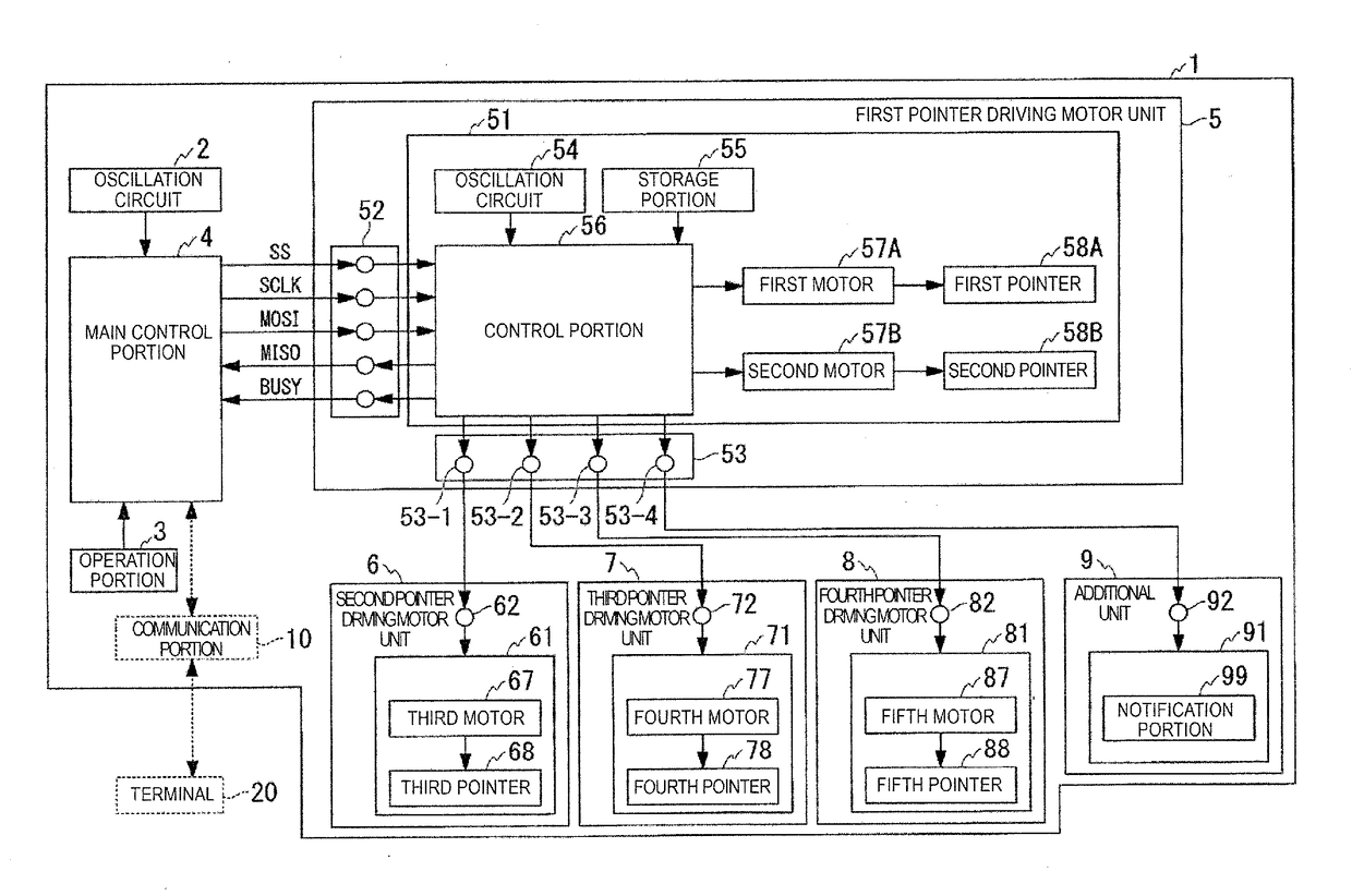
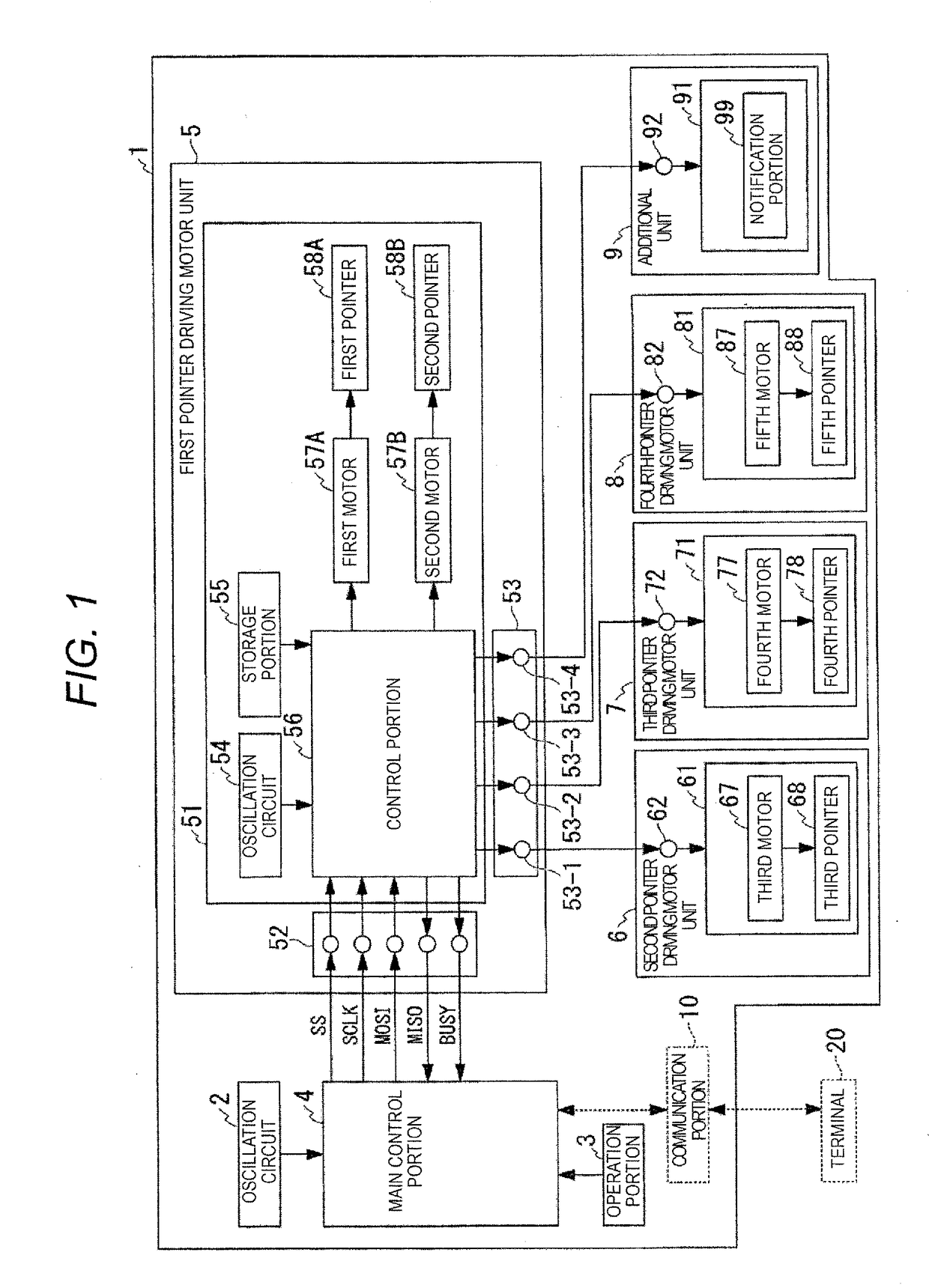
[0026]FIG. 1 is a configuration view illustrating a configuration of a multifunctional electronic device 1 according to the embodiment. In addition, the multifunctional electronic device 1 is, for example, a smart watch. As illustrated in FIG. 1, the multifunctional electronic device 1 is provided with an oscillation circuit 2, an operation portion 3, a main control portion 4, a first pointer driving motor unit 5, a second pointer driving motor unit 6, a third pointer driving motor unit 7, a fourth pointer driving motor unit 8, an additional unit 9, and a communication portion 10. In addition, the multifunctional electronic device 1 is provided with a belt 12 (FIG. 4) which is used for mounting the device on an arm or the like of a user or another fixed location. In addition, the multifunctional electronic device 1 may communicate with a terminal 20, and may send and receive informatio...


PUM


Abstract

A pointer driving motor unit includes: a support body; a pointer which is rotatably supported by the support body; a stepping motor which rotates the pointer; an input portion into which an input signal is put from a main control portion connected to the support body from the outside of the support body; and a control portion which is disposed in the support body, and controls driving of the stepping motor in accordance with the input signal.

Description

RELATED APPLICATIONS[0001]This application claims priority under 35 U.S.C. §119 to Japanese Patent Application No. 2016-000685 filed on Jan. 5, 2016, the entire content of which is hereby incorporated by reference.BACKGROUND OF THE INVENTION[0002]1. Field of the Invention[0003]The present invention relates to a pointer driving motor unit and a control method of the pointer driving motor unit.[0004]2. Description of the Related Art[0005]In JP-A-2002-323577, an electronic clock configured of a time display module and an additional module is disclosed. On the time display module described in JP-A-2002-323577, a crystal vibrator, a MOSIC chip, a wheel train, a motor, and a battery are loaded, and on the additional module, a driving IC for an additional function is loaded. The time display module is configured to have the battery which is a power source that drives a main control portion (microcomputer) loaded thereon, also have a quartz which is a reference clock of a system including t...

Claims


Application Information

Patent Timeline
Patent Type & Authority Applications(United States)
IPC IPC(8): G04C3/14G04B19/04
CPCG04B19/04G04C3/14G04C3/146
Inventor OGASAWARA, KENJIKAWATA, MASAYUKIKOYAMA, KAZUHIRO
Owner SEIKO INSTR INC
Learn More