RFID tag and method of controlling the same

a radiofrequency identification and tag technology, applied in the field of radiofrequency identification (rfid) tags and the same control method, can solve the problems of inefficiency of data transmission speed of rfid tags, and achieve the effect of improving data transmission speed and recognition range, and high speed

Inactive Publication Date: 2017-07-06
ELECTRONICS & TELECOMM RES INST
View PDF0 Cites 25 Cited by
  • Summary
  • Abstract
  • Description
  • Claims
  • Application Information

AI Technical Summary

Benefits of technology

[0014]The present invention is directed to technology for a high speed wide range RFID tag capable of improving a data transmission speed and a recognition range between an RFID tag and an RFID reader by controlling the reflected power as multi-levels through adjustment of a reflection coefficient at the RFID tag, and a method of controlling the same.

Problems solved by technology

That is, for communication between an RFID tag and an RFID reader in the conventional UHF band RFID system, 1 bit is included in one symbol, which leads to inefficiency of data transmission speed of the RFID tag, compared to pulse amplitude modulation(PAM) (multi bits / symbol) having multi-levels.

Method used


Image

  • RFID tag and method of controlling the same
  • RFID tag and method of controlling the same
  • RFID tag and method of controlling the same

Examples


first embodiment

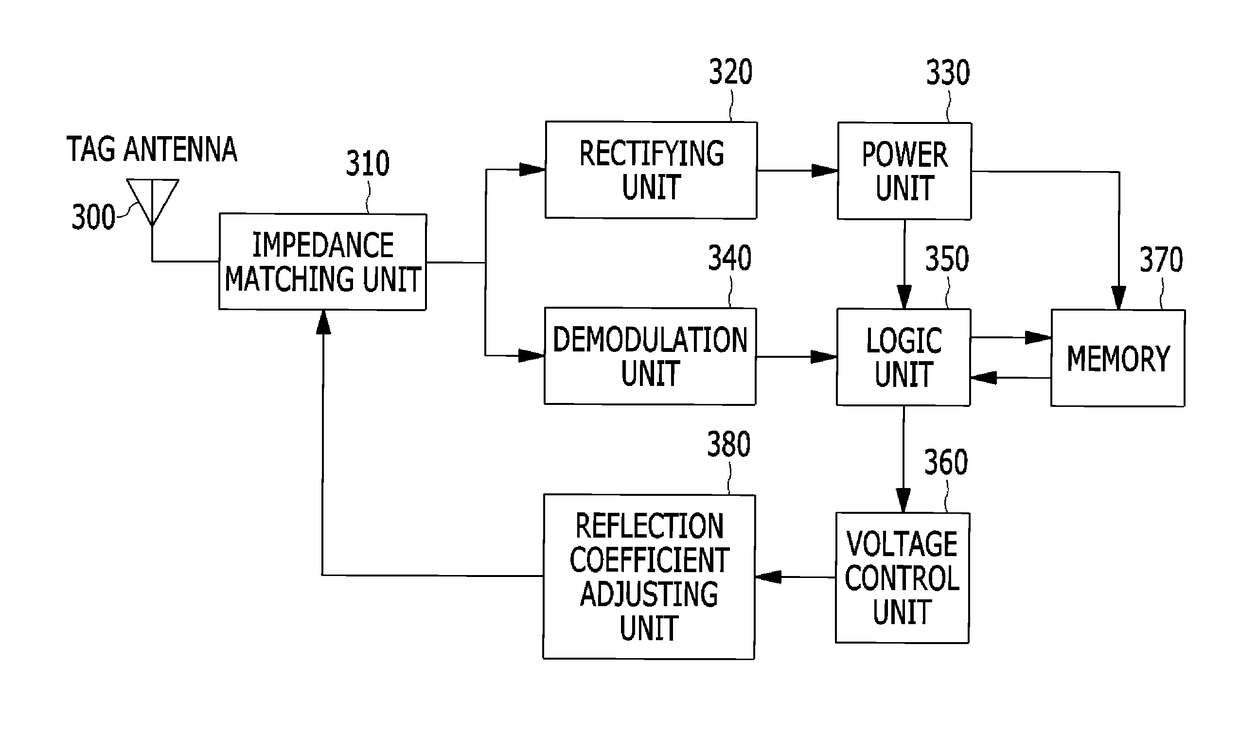
[0047]FIG. 3 is a block diagram illustrating a configuration of an RFID tag according to the present invention.

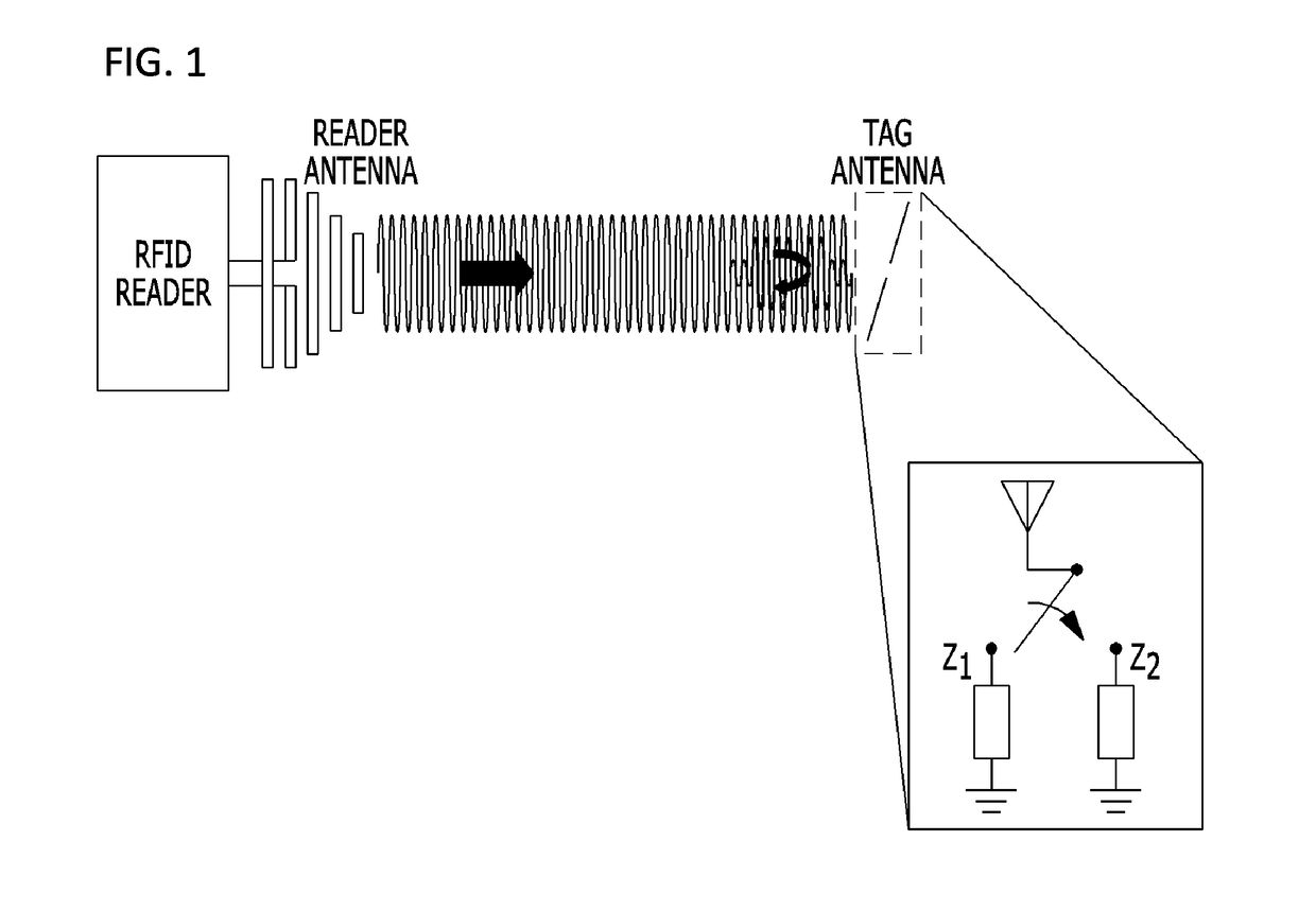
[0048]First, a general passive RFID tag scatters electromagnetic waves transmitted from an RFID reader and returns tag information to the RFID reader, and to this end, an impedance of a tag antenna varies. The variation of impedance of the tag antenna is achieved by switching an impedance value of a modulator in the tag, and in general, a load impedance of the tag has two states.

[0049]As shown in FIG. 3, an RFID tag according to the embodiment of the present invention includes a tag antenna 300, an impedance matching unit 310, a rectifying unit 320, a power unit 330, a demodulation unit 340, a logic unit 350, a voltage control unit 360, a memory 370 and a reflection coefficient adjusting unit 380.

[0050]In contrast to the above-described general passive RFID tag, the RFID tag according to the present invention returns tag information through the reflection coefficient adjust...

second embodiment

[0072]FIG. 9 is a block diagram illustrating a configuration of an RFID tag according to the present invention.

[0073]As illustrated in FIG. 9, an RFID tag according to the second embodiment of the present invention is largely divided into a tag antenna unit and a tag system unit.

[0074]The tag antenna unit includes a tag reception antenna 900 and a tag transmission antenna 910.

[0075]The tag system unit includes a path control unit 920, an impedance matching unit 930, a rectifying unit 940, a power unit 950, a demodulation unit 960, a logic unit 970, a memory 980, a gain adjusting unit 990, a modulation unit 1000, and a variable amplifying unit 1010. The impedance matching unit 930, the rectifying unit 940, the power unit 950, and the demodulation unit 960 have the same configurations and operations as those described in the first embodiment of the present invention shown in FIG. 3, and thus detailed description thereof will be omitted.

[0076]First, a signal transmitted from the RFID r...


PUM


Abstract

Disclosed are a high speed wide range RFID tag capable of improving a data transmission speed and a recognition distance between an RFID tag and an RFID reader by controlling a reflected power as multi levels through adjustment of a reflection coefficient in the RFID tag, and a method of controlling the same. The RFID tag includes a data converting unit configured to convert stored RFID serial tag data into a number of multi-level parallel data according to a request of an RFID reader, a reflection coefficient adjusting unit configured to generate a plurality of reflection coefficients corresponding to a number of the converted parallel data, and a transmitting unit configured to transmit a number of the multi-level parallel data according to the generated plurality of tag reflection coefficients through an antenna to the RFID reader.

Description

CROSS-REFERENCE TO RELATED APPLICATION[0001]This application claims priority to and the benefit of Korean Patent Application No. 10-2016-0000652, filed on Jan. 4, 2016, the disclosure of which is incorporated herein by reference in its entirety.BACKGROUND[0002]1. Field of the Disclosure[0003]The present invention relates to a technology for a radio-frequency identification (RFID) tag and a method of controlling the same, and more particularly, to a high speed wide range RFID tag capable of improving a data transmission speed and a recognition distance between an RFID tag and an RFID reader by controlling reflected power as multi-levels through adjustment of a reflection coefficient at the RFID tag, and a method of controlling the same.[0004]2. Discussion of Related Art[0005]In general, RFID technology is a technology in which a tag is attached to each object to identify a unique identifier (ID) of the object in a wireless manner and collect, store, process and track relevant informa...

Claims


Application Information

Patent Timeline
Patent Type & Authority Applications(United States)
IPC IPC(8): G06K7/10G06K19/07
CPCG06K7/10158G06K2007/10495G06K19/0702G06K19/0726
Inventor JUNG, JAE YOUNGPARK, CHAN WONKIM, HYUN SEOKBANG, HYO CHANCHOI, WON KYU
Owner ELECTRONICS & TELECOMM RES INST
Why Eureka
Try Eureka