

Reflection-Based RF Phase Shifter
- Summary
- Abstract
- Description
- Claims
- Application Information
AI Technical Summary
Benefits of technology
Problems solved by technology
Method used
Image

Examples
Embodiment Construction
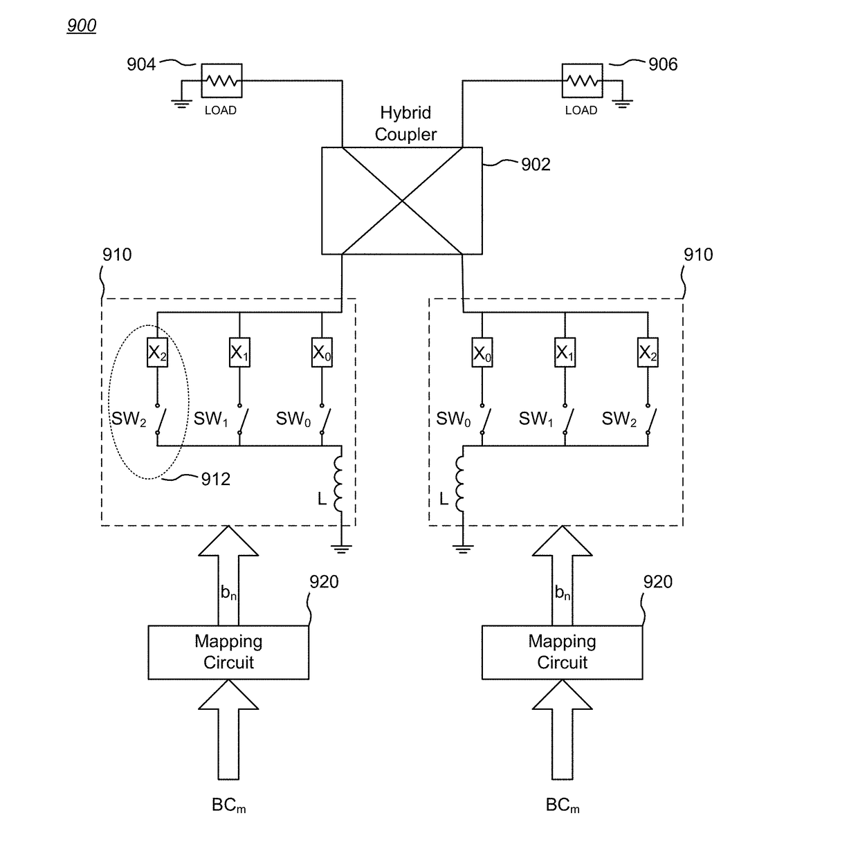
[0050]The invention encompasses various embodiments of multi-reflective phase shifters which provide reduced root-mean-square (RMS) phase error, which can be optimized for a desired frequency band, which can compensate for process variations arising during manufacture, and which can help offset system level performance shortfalls.
[0051]Thermometric Coding for Equidistant Phasor Generation
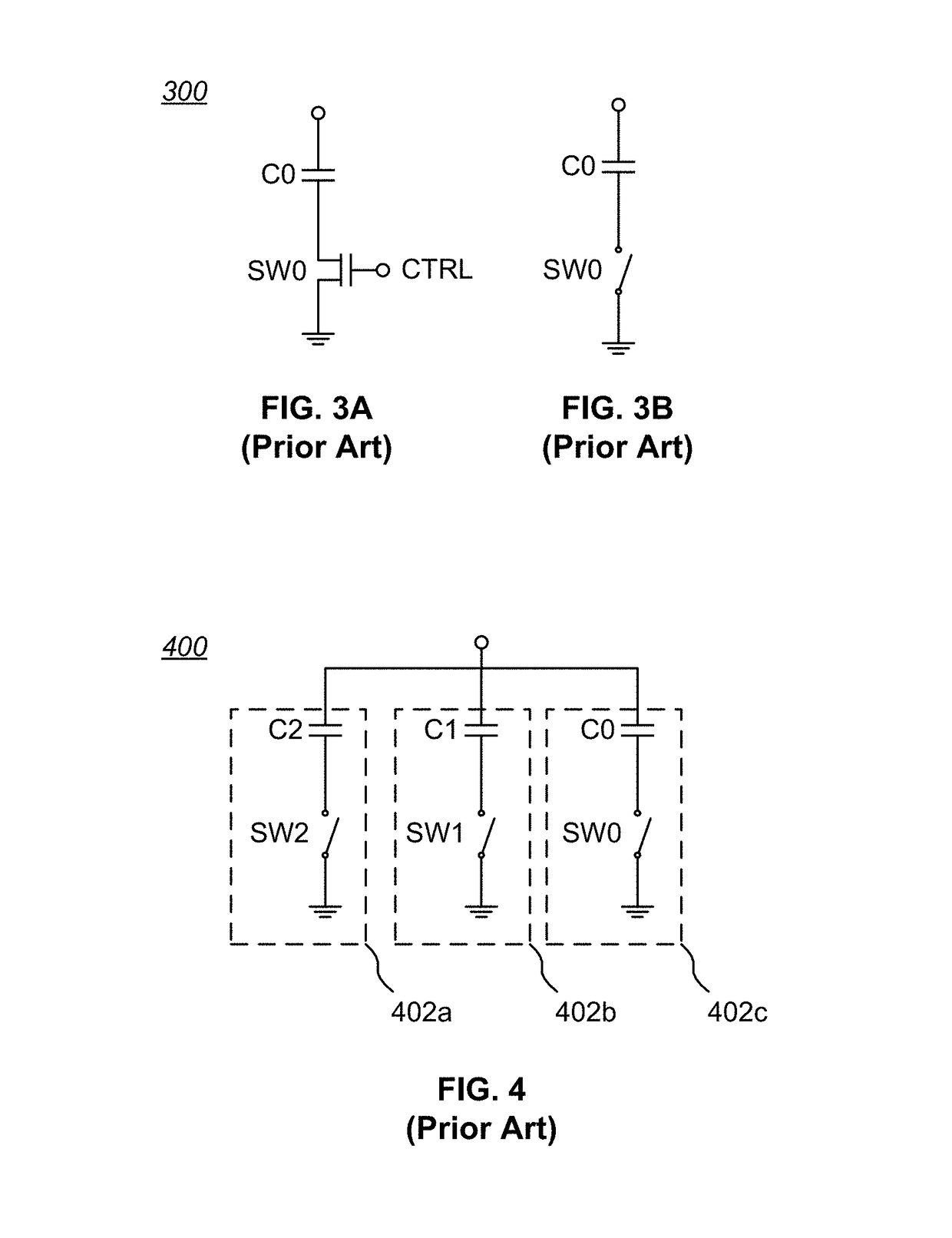
[0052]Use of a single hybrid coupler with multiple switchable reactive elements to achieve multiple equidistant phase shifts is difficult with conventional designs because capacitance (or, more generally, reactance) values do not increase uniformly, and each switchable reactive element is affected by loading of its own OFF state phase value as well as the particular ON / OFF state of other switchable reactive elements. A close consideration of the circuit shown in FIG. 4 for switching capacitor-based reactive elements into and out of circuit discloses that a simple binary scheme for controlling such r...
PUM
 Abstract
Description
Claims
Application Information