Electric tool

a technology of electric tools and electric strikes, applied in the field of electric tools, can solve the problems of not being able to achieve the optimal shape of electric tools, especially electric striking tools, and achieve the effect of improving the service life and reducing the cost of electric tools

Active Publication Date: 2017-07-06
HITACHI KOKI CO LTD
View PDF3 Cites 10 Cited by
  • Summary
  • Abstract
  • Description
  • Claims
  • Application Information

AI Technical Summary

Benefits of technology

[0017]According to the invention, an electric tool as follows is achieved. Namely, the electric tool has a motor size not damaging the operability, and is able to a

Problems solved by technology

Thus, regarding the shape of the motor core of Patent Literature 1, where the shape is determined without setting the target performance of

Method used


Image

  • Electric tool
  • Electric tool
  • Electric tool

Examples


Embodiment Construction

[0026]In the following, the preferred embodiments of the invention are described in detail with reference to the accompanying drawings. Same or equivalent forming elements, components, processes, and the like shown in the respective figures are marked with the same reference symbols. In addition, repeated descriptions are appropriately omitted. Also, the embodiments merely serve as exemplary examples, instead of limitations of the invention. All the features described in the embodiments or combinations thereof are not necessarily the essence of the invention.

[0027]As an embodiment of the electric tool of the invention, an application of a hammer drill as an electrical striking tool is described.

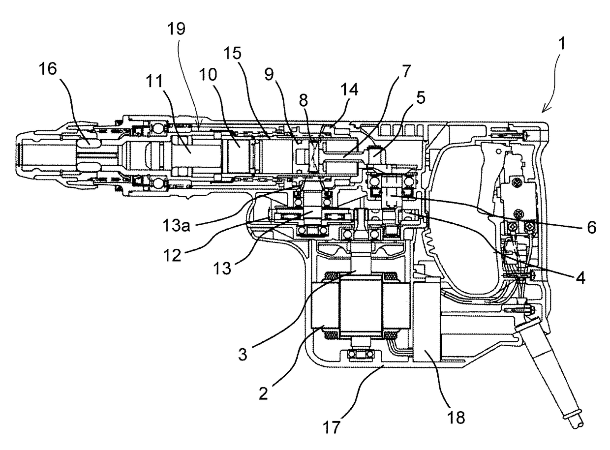
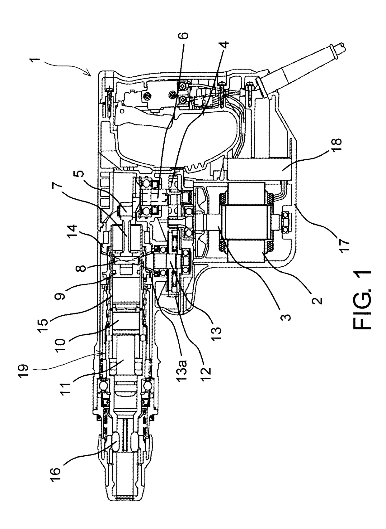
[0028]As shown in FIG. 1, a hammer drill 1 includes: a brushless motor 2 configured as a driving force and stored in a housing 17; a rotary striking mechanism unit 19 converting a rotational force of the brushless motor 2 into a striking force and applying the striking force to a tip tool (no...


PUM


Abstract

An electric tool is provided with a rotary striking mechanism unit converting the rotational force of a brushless motor to a striking force and applying the striking force to a tip tool. The required rated input of the motor is 1000-1300 W, the motor speed under fixed speed control is 16800±10% (min−1), and the variable Ku, which relates to the motor, is defined by the following expression Ku={(stator core outer diameter)2×(stator core lamination thickness)×(total tooth width)×(rotor outer diameter)}÷{(rated input)×(motor speed under fixed speed control)}, wherein the stator core outer diameter, the stator core lamination thickness, the total tooth width and the rotor outer diameter are shown in mm, the rated input is shown in W, the motor speed is shown in min−1, and the Ku value of the motor is set to 14.6←Ku←21.8.

Description

BACKGROUND OF THE INVENTION[0001]1. Field of the Invention[0002]The invention relates to an electric tool, such as a hammer drill, an impact drill, an impact wrench, or the like, where a brushless motor is used as a driving source.[0003]2. Description of Related Art[0004]Electric tools, particularly electric striking tools, such as hammer drill have a mechanical section that is complicated and has a significant amount of components.[0005]To maximize the performance of the mechanical section to its full extent, it is very important for the mechanical section to match motor performance.[0006]For example, to solidly match the mechanical section with motor performance, motor speed control utilizing electronic control is applied to suppress variation of a target motor speed within a range of plus or minus a few percentage points In addition, in order to continuously perform demanding operations, a rated input (W) of the device is also important. Based on a target value, motor winding, th...

Claims


Application Information

Patent Timeline
IPC IPC(8): H02K21/16B25D16/00H02K29/00H02K1/14H02K1/27H02K3/18B25D11/00B25F5/00
CPCH02K21/16B25D11/00B25D16/00B25F5/00H02K2213/03H02K1/2706H02K3/18H02K29/00B25D2250/095H02K1/146B25D2211/068
Inventor TANIMOTO, HIDEYUKI
Owner HITACHI KOKI CO LTD
Why Eureka
Try Eureka