Digital camera control system

a control system and digital camera technology, applied in the field of control systems, can solve the problems of insufficient video image contrast to support character recognition, fixed exposure settings will not provide the image quality, brightness and contrast required, and may not be best for first adjustments

Active Publication Date: 2017-07-06
ALVES JAMES
View PDF9 Cites 29 Cited by
  • Summary
  • Abstract
  • Description
  • Claims
  • Application Information

AI Technical Summary

Benefits of technology

[0010]A camera control system is described that meets the demanding needs of high speed traffic and other imaging applications. The system relies upon environmental, geographic, illumination and electronic sensor response models that provide optimized settings for a given geographic location, camera direction relative to a subject, time of day, time of year and wide range of weather conditions. The subject of the image includes a background and a feature on the background that is to be detected and characterized. In one embodiment the subject is a license plate on a vehicle and the feature to be detected and characterized is text on the license plate. In another embodiment the minimum contrast required to recognize the feature on the background is further used to set the exposure parameters. The model uses environmental parameters coupled with a detailed illumination models to preset the camera for the conditions at the particular time, location and orientation that the imaging occurs. Through the use of models and known environmental factors the controller is able to set optimized image sensor parameters a priori. There is no need to continuously take images to sense the possible range of vehicle and plate radiance levels or read radiance levels from an external light sensor. The camera is always ready for the particular camera location, direction, environmental factors and particular lighting conditions.

Problems solved by technology

However portions of license plates that are in shadows (or during low nighttime illumination conditions) often lack enough video image contrast to support character recognition.
Fixed exposure settings will not provide the image quality and brightness and contrast required to read the plate information.
In addition the first portion of the vehicle to appear in the camera's field of view may not be indicative of the irradiance levels seen at the end of the vehicle so first adjustments may not be best.
Both of these systems have drawbacks.
External sensors add cost and complexity to the system and are often difficult to install in the optimum location to perform their light measurement function.
Systems that use pixel value measurements for camera control suffer from time lags between when the light measurements are made versus when the camera gain control changes take affect and the relatively slow sampling rates of the pixel data relative to rapidly moving vehicles.
In addition, the uncertainty of which pixel values correspond to actual license plate light levels (rather than the myriad of other radiance levels that can appear in the scene) means that the control input has a high uncertainty.
This may be difficult or impossible to achieve if the vehicle is moving at high speed and adds to the storage requirements of the system since multiple images must be saved until a determination as to which image is best for plate legibility.

Method used


Image

  • Digital camera control system
  • Digital camera control system
  • Digital camera control system

Examples


Embodiment Construction

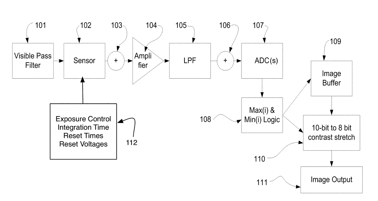
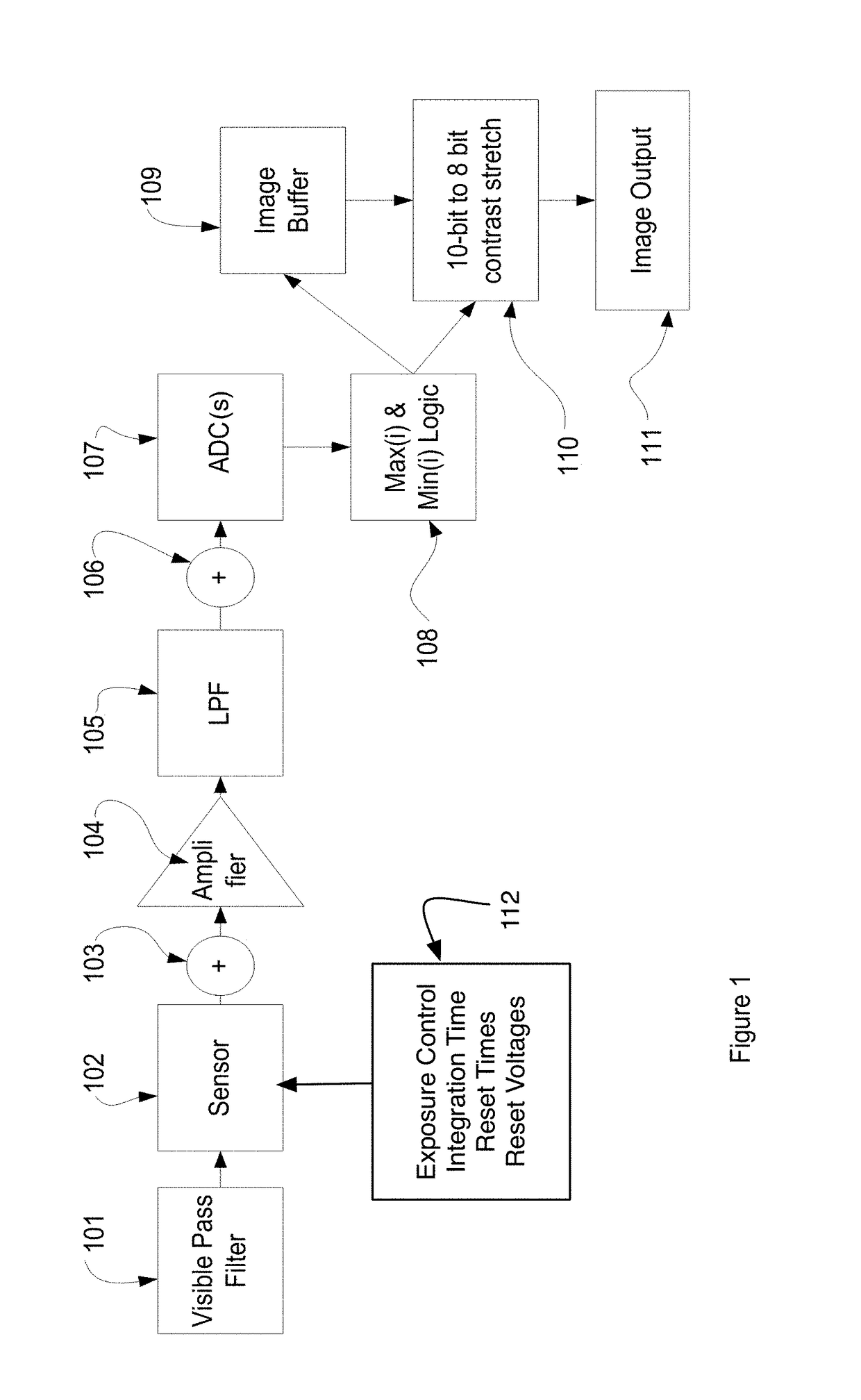
[0042]The present invention is a set of models and algorithms for estimating irradiance of an object to be imaged as a function of environmental factors, the resulting radiance of the object and irradiance upon an imaging sensor and control algorithms for the sensor based upon the environmental factors and particular imaging requirements. In the exemplary case the requirements are contrast sufficient to recognize characters upon a vehicle license plate tag. The license plate features of interest are the background of the licenses plate, white being the brightest possible plate background, the numeric characters of the plate typically larger and black and the state or country designation lettering. The imaging requirements are to have sufficient contrast between the license plate background and the numeric character and the state designation characters.

[0043]FIG. 1 depicts a camera typical of which the invention may be practiced. The camera consists of a near UV through near IR wavel...


PUM


Abstract

A digital camera control system that requires no light sensors is described. The control system relies on modeled external environmental geophysical solar parameters, geometric relationships between the object to be imaged and surrounding potentially shadowing objects, the material properties of the object to be imaged such as reflectivity are combined to produce the estimated irradiance on a camera sensor for the particular time of day, date and geometric relationship between the object and the sun. The calculated irradiance on the image sensor for the background of the object of interest and a feature to be recognized provide a contrast. The signal to noise requirements for the feature recognition are used to determine a minimum required contrast transfer function for the sensor. Control parameters for the sensor are then determined to meet the minimum contrast requirements. The system therefore provides a method to rapidly determine an optimum camera settings for any time of day and ensures the camera is always ready to capture at least the minimum required contrast image of a fast moving transient object. The system is demonstrated for use in a license plate imaging application.

Description

BACKGROUND OF THE INVENTION[0001]Technical Field[0002]The present invention relates to a control system to optimize imaging parameters of a digital video camera.[0003]Related Background Art[0004]High-speed digital cameras have become commonly used in toll collection and traffic law enforcement applications. These cameras must acquire images of fast moving objects with an image quality sufficient to identify the object(s) of interest. In the case of vehicles on a motorway, the objective is often to be able to identify the vehicle by clearly imaging the vehicle's license plate. Typically both the plate's alpha-numerics and the state name must be legible in the image. The larger alpha-numerics are often, but not always, in block print in a uniform color on a uniform or nearly uniform background. The state names however are often much smaller font sizes and printed in different colors and in various scripts. Generally modern license plates are designed more for aesthetics rather than to...

Claims


Application Information

Patent Timeline
Patent Type & Authority Applications(United States)
IPC IPC(8): H04N5/376G06K9/46G06K9/00H04N5/378G06K9/32G06V10/60
CPCH04N5/3765H04N5/378G06K9/4661G06K9/00442G06K9/325G06V20/63G06V10/60H04N23/6811H04N23/684H04N23/71H04N23/73H04N23/74H04N23/76
Inventor ALVES, JAMES
Owner ALVES JAMES
Why Eureka
Try Eureka