
Fin for heat exchanger

a heat exchanger and offset fin technology, which is applied in the field of heat exchangers, can solve the problems of reducing the structural integrity of the heat exchange core, increasing the weight of the offset fin, and reducing the maximum efficiency of the fin, so as to maintain the structural integrity minimize the weight of the heat exchanger, and maximize the heat transfer efficiency

Active Publication Date: 2017-07-13
HANON SYST
View PDF7 Cites 2 Cited by
  • Summary
  • Abstract
  • Description
  • Claims
  • Application Information

AI Technical Summary

Benefits of technology

The present invention is about a new design for a fin for a heat exchanger that improves heat transfer and keeps the structure strong while minimizing the weight, materials used, and manufacturing costs.

Problems solved by technology

However, louvered fins increase fin weight, density, and materials employed, which can be undesirable.
Louvered fins and split mini louvered fins reduce the structural integrity of the heat exchange core which can be problematic, especially in scenarios where greater loads are applied to the heat exchange core.
Additionally, the mini louvered fins typically do not extend an entire height of the planar portions of the fins due to design constraints which limits maximum efficiency of the fins.
Furthermore, because the louvres protrude from the planar portions of the fins, a cross-sectional flow area between adjacent planar portions of the fins is compromised, which may inhibit air flow through the fins.

Method used


Image

  • Fin for heat exchanger
  • Fin for heat exchanger
  • Fin for heat exchanger

Examples


Embodiment Construction

[0019]The following detailed description and appended drawings describe and illustrate various embodiments of the invention. The description and drawings serve to enable one skilled in the art to make and use the invention, and are not intended to limit the scope of the invention in any manner.

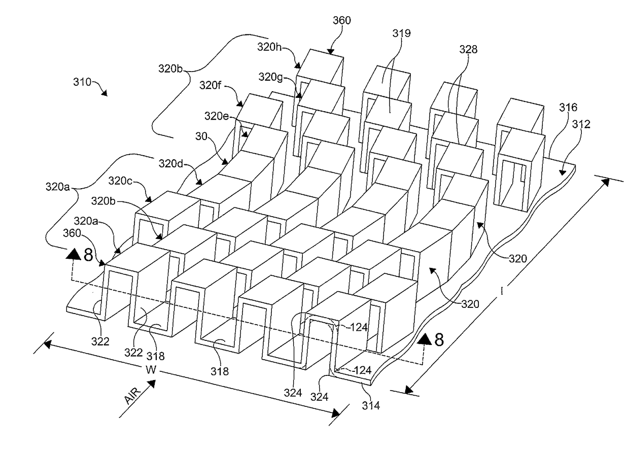
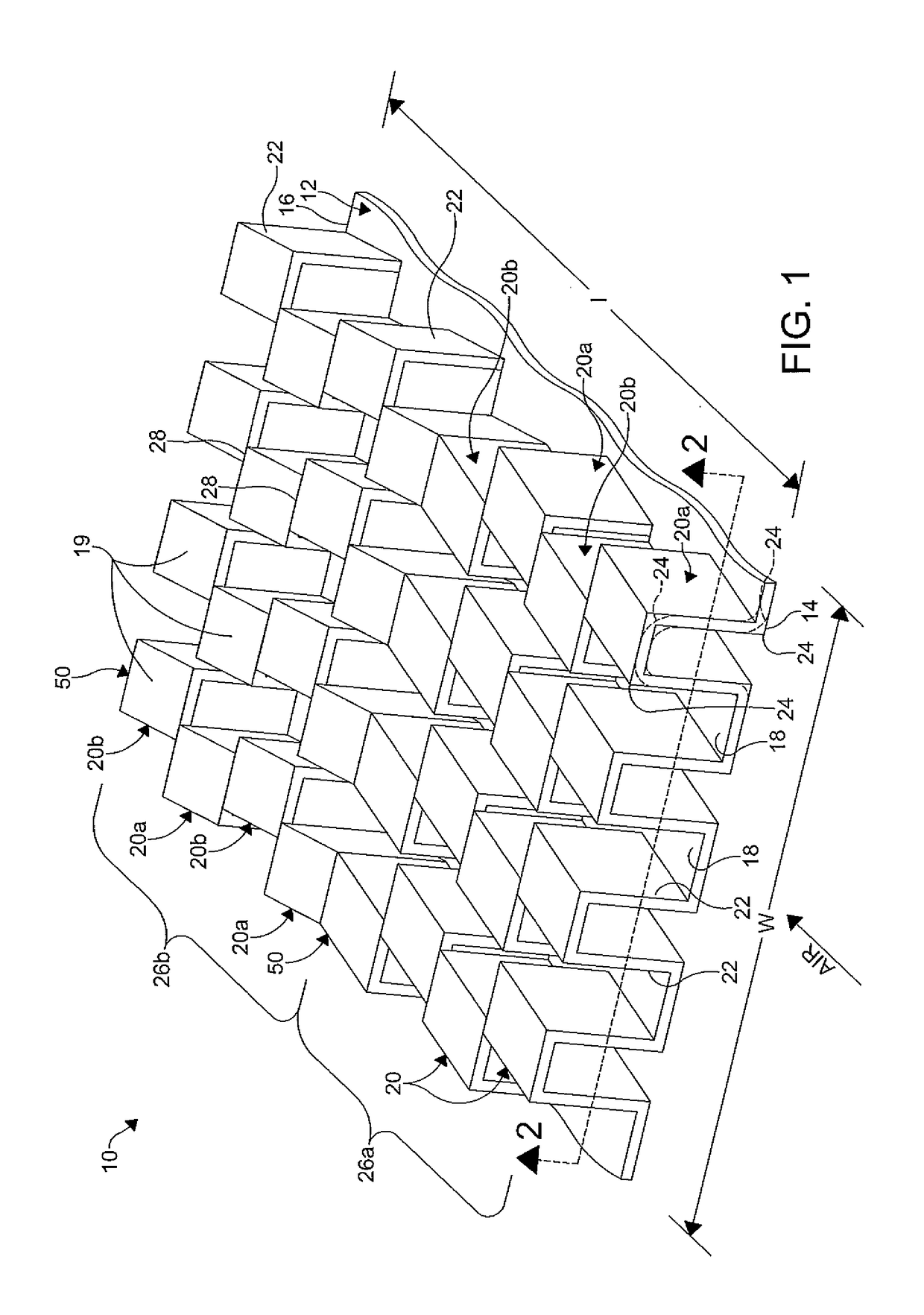
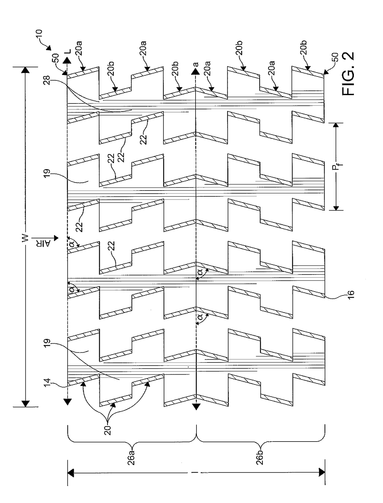
[0020]FIGS. 1-8 illustrate various embodiments of lanced offset fins 10, 110, 210, 310. The fins 10, 110, 210, 310 are configured for use between plates or tubes in a heat exchange core of a heat exchanger (not shown) of a motor vehicle. The fins 10 facilitate a transfer of heat between air flowing therethrough and a fluid flowing through the plates or the tubes of the heat exchanger. The air flows through the fins 10, 110, 210, 310 in a direction indicated by the arrow. In a non-limiting example, the heat exchanger can be a water-cooled charge air cooler (WCAC) for use in a charge air circuit of the motor vehicle. However, it is understood the fins 10, 110, 210, 310 can be employed with any t...


PUM


Abstract

A fin for a heat exchanger includes a member and a first row formed in the member. The first row having a plurality of valley sections alternating with a plurality of crest sections. A plurality of walls is interposed between and integrally joins the plurality of valley sections and the plurality of crest sections. At least one of the plurality of walls of the first row is angled with respect to a lateral axis of the member. A second row is formed in the member, the second row having a plurality of valley sections alternating with a plurality of crest sections and a plurality of walls interposed between and integrally joining the plurality of valley sections to the plurality of crest sections.

Description

FIELD OF THE INVENTION[0001]The invention relates to a heat exchanger, particularly to a lanced offset fin for a heat exchanger having angled walls.BACKGROUND OF THE INVENTION[0002]As is commonly known, heat exchangers are employed to transfer heat between a fluid flowing through the heat exchanger and air. Heat exchangers typically contain a heat exchange core having a plurality of tubes or plates interposed with a plurality of fins. Air flows through the fins of the heat exchange core. The fins facilitate heat transfer between the fluid of the heat exchanger and the air. In certain applications, the fins can additionally provide structural support to the heat exchange core.[0003]Various types of fins are known in the art to improve the heat transfer efficiency of the fins. For example, certain types of fins include louvres on a planar portion of the fin to increase turbulence. Increased turbulence increases a heat transfer coefficient between the surface of the fin and the air flo...

Claims


Application Information

Patent Timeline
Patent Type & Authority Applications(United States)
IPC IPC(8): F28F1/10
CPCF28F1/10F28F3/027F28F1/128F28F1/126F28F3/025
Inventor SOMHORST, LEOFABIAN, PETRJOYCE, STEPHENBURSIK, MAREKSIKORA, TOMAS
Owner HANON SYST
Learn More