A loop heat pipe geothermal mining system with adjustable working fluid circulation flow

A working fluid circulation and heat pipe type technology, applied in the field of loop heat pipe type geothermal mining system, can solve the problems of low heat transfer efficiency and achieve the effects of avoiding too deep liquid pool, maximizing heat transfer efficiency, and avoiding carryover effect

Active Publication Date: 2019-06-28
GUANGZHOU INST OF ENERGY CONVERSION - CHINESE ACAD OF SCI
View PDF6 Cites 3 Cited by
  • Summary
  • Abstract
  • Description
  • Claims
  • Application Information

AI Technical Summary

Problems solved by technology

In addition, the liquid pool accumulated in the evaporation section is too deep, the pressure at the deeper liquid level is higher, and it is in a supercooled state, that is, a non-boiling state. This part of the evaporation section is filled with a non-boiling liquid column. The temperature of the rock reaches equilibrium, so that the large area at the bottom of the evaporation section will not absorb heat from the outside of the tube, resulting in low heat transfer efficiency

Method used


Image

  • A loop heat pipe geothermal mining system with adjustable working fluid circulation flow
  • A loop heat pipe geothermal mining system with adjustable working fluid circulation flow
  • A loop heat pipe geothermal mining system with adjustable working fluid circulation flow

Examples


Embodiment 1

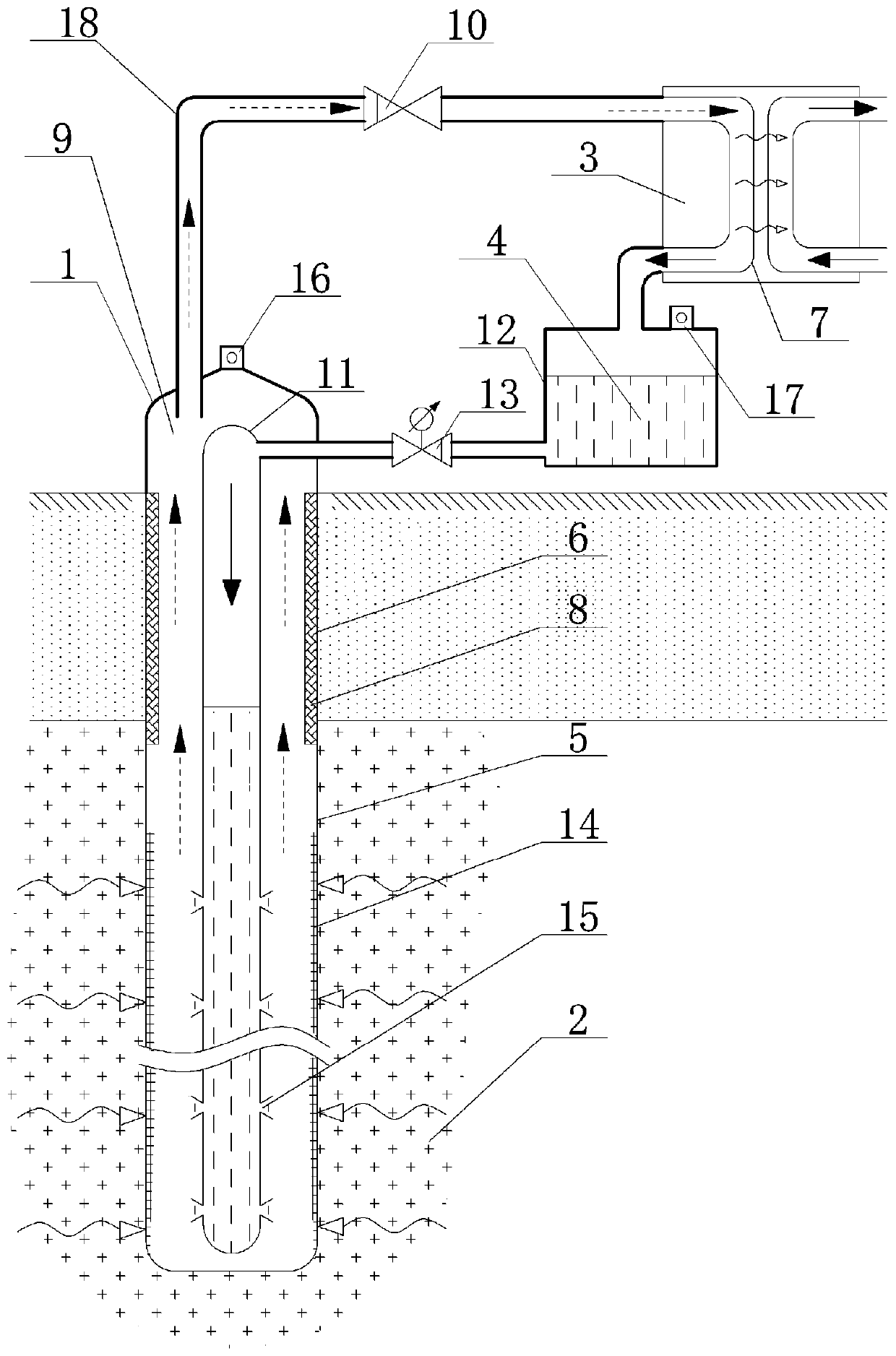
[0028] Such as figure 1 with figure 2As shown, the sleeve-type loop heat pipe 1 includes an outer sleeve 9, an inner sleeve 11 and a connecting pipe. The one-way valve 10 or the steam pump, the connecting pipe and the outer casing 9 are connected, the inner casing 11 is located in the outer casing 9, and the part of the outer casing 9 located in the high-temperature heat storage 2 of the formation is provided with an evaporation section 5, and the outer casing 9 Micro-grooves 14 are provided on the inner wall corresponding to the region of the evaporation section 5, and the outer sleeve 9 is provided with an insulating section 6 at the part outside the high-temperature heat storage 2, and the connecting pipe is provided with an insulating section 6, and the inner sleeve 11 tube Perforations 15 are arranged on the wall corresponding to the area of ​​evaporation section 5. The aperture and distribution density of the perforations 15 are determined according to the circulation ...

Embodiment 2

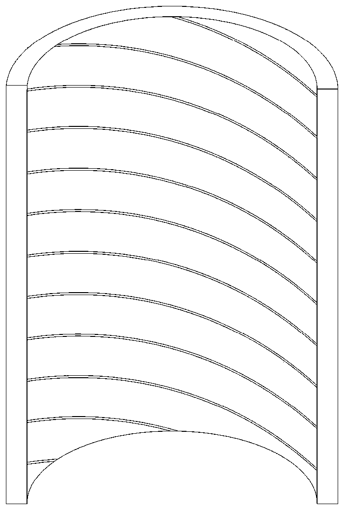
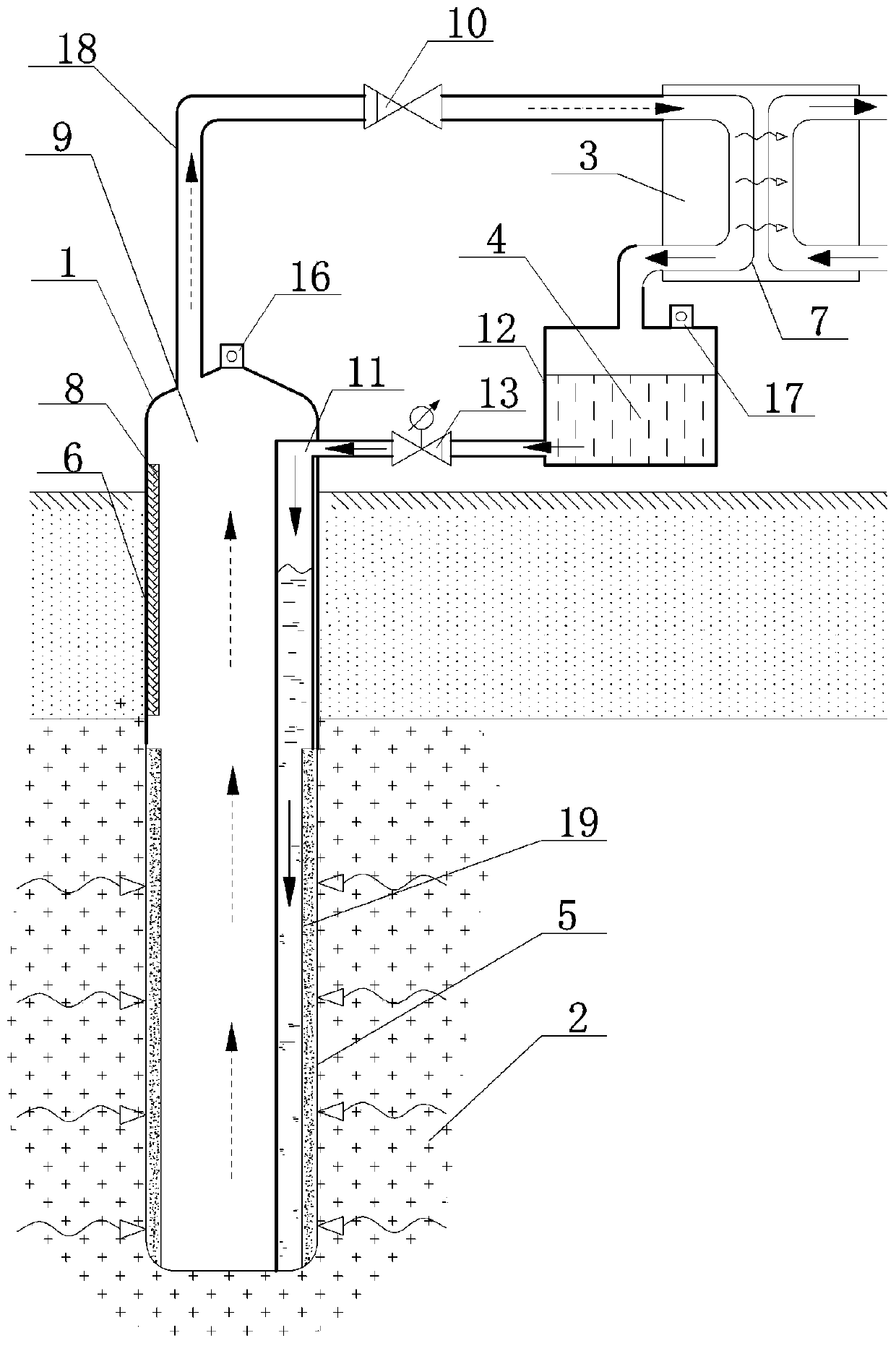
[0044] The casing type loop heat pipe 1 includes an outer casing 9, an inner casing 11 and a connecting pipe, and the top of the inner casing 11 is sequentially connected with the one-way throttle valve 13, the liquid storage tank 12, the surface heat exchanger 3, and the one-way valve. 10 or a steam pump, connecting pipe and outer casing 9, the inner casing 11 is located in the outer casing 9, and the part of the outer casing 9 located in the high-temperature heat storage 2 of the formation is provided with an evaporation section 5, and the outer casing 9 corresponds to the evaporation section The inner wall of the area 5 is provided with micro-grooves 14 and porous metal layer 19 in turn, and the part of the outer casing 9 located outside the high-temperature heat storage 2 is provided with an insulating section 6, and the connecting pipe is provided with an insulating section 6, and the porous metal The layer 19 is provided with a porous metal layer slit 20 parallel to the a...

Embodiment 3

[0050] Such as Figure 5 As shown, the sleeve type loop heat pipe 1 includes an outer sleeve 9, an inner sleeve 11 and a connecting pipe, and the top of the outer sleeve 9 is connected with a one-way throttle valve 13, a liquid storage tank 12, a ground heat exchanger 3, a one-way The valve 10 or the steam pump and the connecting pipe are connected end to end in sequence, the bottom and top of the inner sleeve 11 are open and located at the upper part of the outer sleeve 9, and the gap between the outer sleeve 9 and the inner sleeve 11 is provided with a return section The part of the outer casing 9 located in the high-temperature heat storage 2 of the formation is provided with an evaporation section 5, and the part of the outer casing 9 located outside the high-temperature heat storage 2 is provided with an adiabatic section 6, and the inner casing 11 and the outer casing 9 An annular gate 22 is provided in the area where the gap is located at the junction of the evaporation...


PUM


Abstract

The invention discloses a loop heat pipe type terrestrial heat exploitation system with adjustable and controllable working medium circular flow. The loop heat pipe type terrestrial heat exploitation system comprises a casing pipe type loop heat pipe, an earth surface heat exchanger and a liquid storage box. The earth surface heat exchanger and the liquid storage box are both located on the ground. The casing pipe type loop heat pipe comprises an evaporation section, a heat insulation section and a backflow section. The evaporation section is located in a high temperature heat reservoir. The earth surface heat exchanger is provided with a condensation section, and the condensation section and the outside carry out heat exchange. A one-way valve or a steam pump is arranged between the heat insulation section and the condensation section. A one-way throttle valve is arranged between the liquid storage box and the backflow section. The evaporation section, the heat insulation section, the condensation section, the liquid storage box and the backflow section are communicated in sequence end to end. Working medium fluid of the liquid storage box enters the evaporation section through the backflow section, and the liquid working medium fluid entering the evaporation section generates film boiling after absorbing heat. According to the loop heat pipe type terrestrial heat exploitation system, the working medium fluid of the liquid storage box passes through the backflow section, the liquid phase backflow mode and the boiling mode of the evaporation section are controlled, the effective filling factor of the terrestrial heat pipe can be adjusted in real time, and therefore terrestrial heat energy is stably and efficiently extracted.

Description

technical field [0001] The invention relates to geothermal energy mining technology in the field of energy, in particular to a loop heat pipe type geothermal mining system with adjustable working fluid circulation flow. Background technique [0002] Geothermal energy is a clean and renewable energy. The development and utilization of geothermal energy, especially the development of deep geothermal resources, has gradually become one of the key directions of new energy development in the world. At present, the development and utilization of geothermal resources not only includes direct utilization such as heating and planting, but also can realize geothermal cooling and power generation of medium and high temperature geothermal resources. In addition, the development of geothermal resources has also developed from medium and shallow hydrothermal resources to deeper strata such as deep geothermal and hot dry rock resources. [0003] The heat pipe utilizes the phase change of ...

Claims


Application Information

Patent Timeline
Patent Type & Authority Patents(China)
IPC IPC(8): F24T10/17F28D15/02F28D15/04
CPCY02E10/10
Inventor 蒋方明李德威曹文炅黄文博黄小雪陈棋
Owner GUANGZHOU INST OF ENERGY CONVERSION - CHINESE ACAD OF SCI
Why Eureka
Try Eureka