Combined oil well pump for preventing well flushing from polluting oil layer

An oil well pump and combined technology, applied in the field of combined oil well pumps, can solve the problems of long pump inspection period, limitations and hidden dangers, oil layer pollution, etc., and achieve the effect of simple structure and strong applicability

Active Publication Date: 2019-05-21
天津五一泰科机电科技有限公司
View PDF11 Cites 4 Cited by
  • Summary
  • Abstract
  • Description
  • Claims
  • Application Information

AI Technical Summary

Problems solved by technology

In the pollution-free well flushing device disclosed in the above patent documents, during the production process of the oil well, the packer separates the oil casing annulus up and down, resulting in the failure to measure the production data such as the dynamic fluid level
The device does not specify what kind of packer to use. Conventional packers are often difficult to release due to water scaling and other reasons after a long downhole time.
Due to the advancement of technology and product quality, oil well maintenance, etc., the pump inspection cycle is getting longer and longer, and the problem of packer unsealing failure is more prominent. Once the packer cannot be unsealed, it will cause the well to be overhauled
At the same time, the device cannot realize card layer mining, so the application limitations and hidden dangers are great
[0003] Oil production and well flushing urgently need to solve the bottleneck problem that the well flushing fluid enters the oil layer and causes oil layer pollution, which affects the production efficiency of the oil well

Method used


Image

  • Combined oil well pump for preventing well flushing from polluting oil layer
  • Combined oil well pump for preventing well flushing from polluting oil layer
  • Combined oil well pump for preventing well flushing from polluting oil layer

Examples


Embodiment Construction

[0014] Below in conjunction with preferred embodiment, the specific implementation mode provided according to the present invention is described in detail as follows:

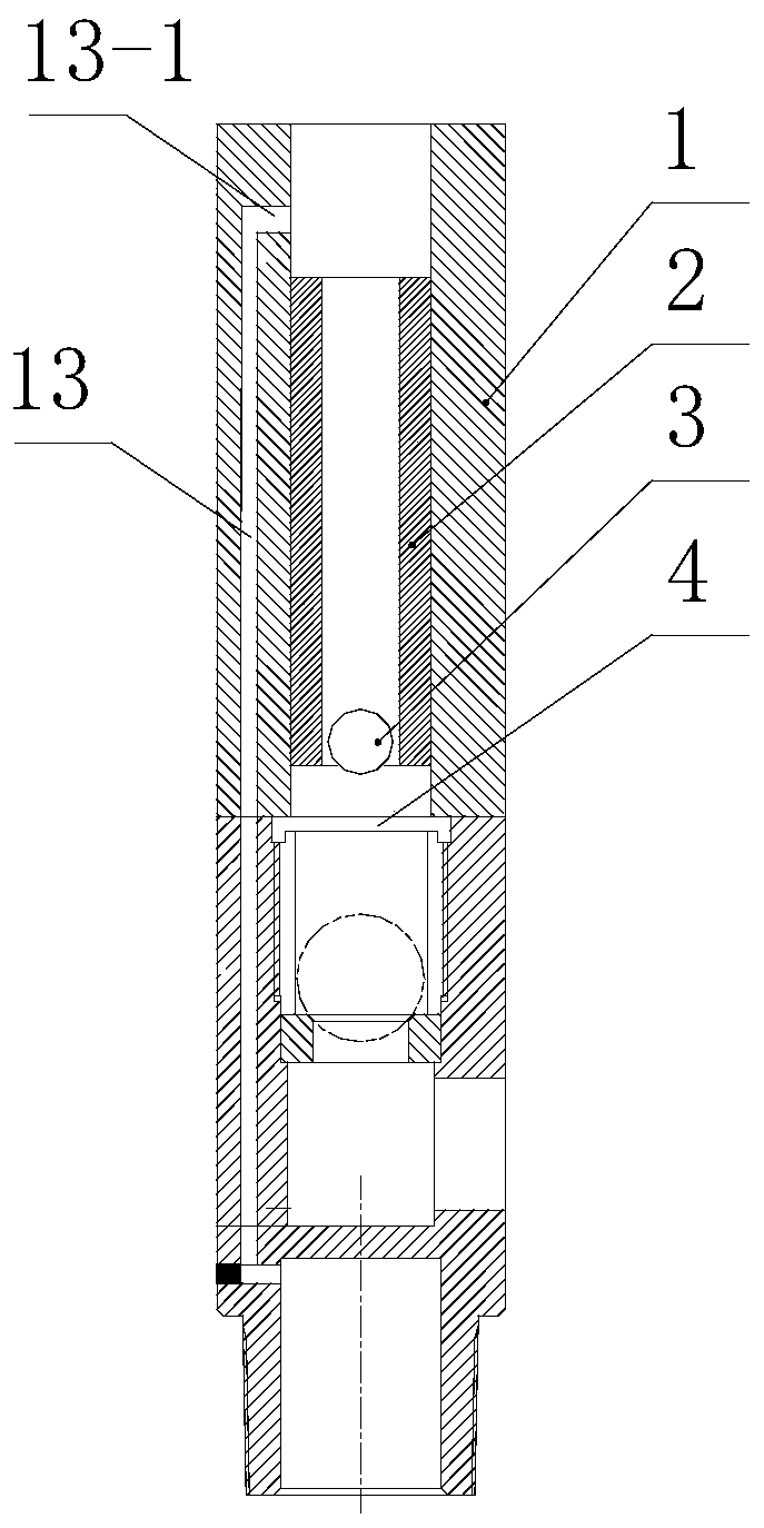
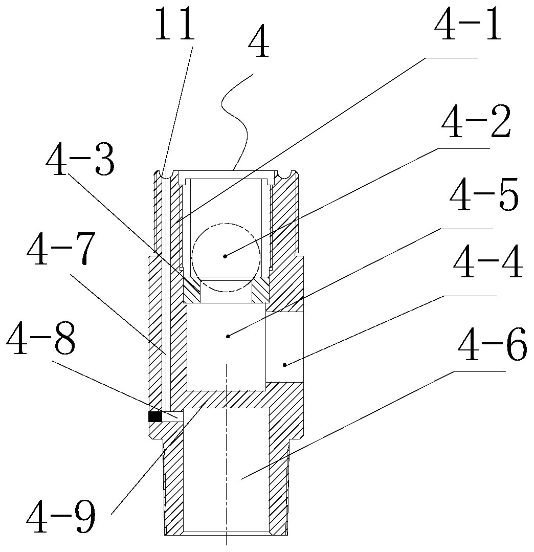
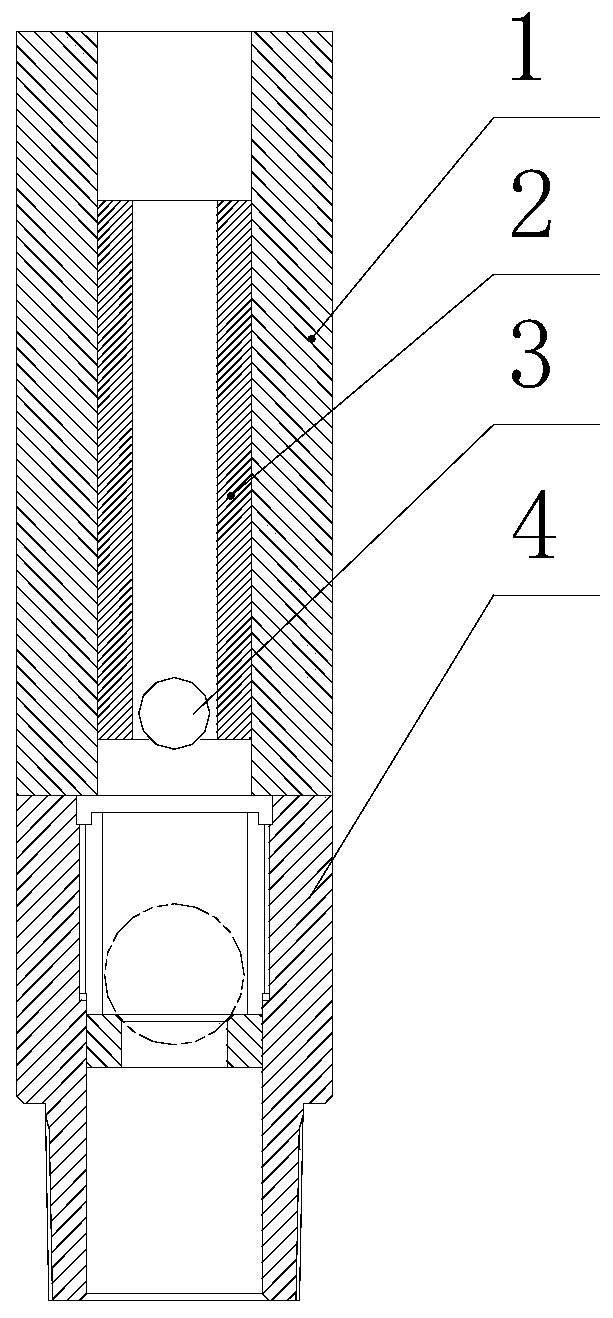
[0015] see attached figure 1 , this embodiment discloses a combined oil well pump for preventing well washing from polluting the oil layer, including an oil well pump barrel 1, a plunger assembly 2, a floating valve 3, a fixed valve 4, a diaphragm packer 5 and a plug 12 The pump barrel wall of the oil well pump is provided with a pump barrel diversion channel 13, the upper end of the pump barrel diversion channel is connected with a radial small hole 13-1 communicating with the inner cavity of the pump barrel, and the diameter of the upper end of the diversion channel is connected The location of the small hole is that when the plunger is at the bottom dead center, the radial small hole should communicate with the inner cavity of the pump barrel, so that the plunger is just connected with the inner cavity of th...


PUM


Abstract

The invention relates to a combined oil well pump capable of preventing well flushing from polluting an oil layer. The combined oil well pump an oil pump cylinder, a plunger assembly, a fixed valve, adiaphragm packer and a plug. The combined oil well pump is characterized in that a pump cylinder flow guide channel is arranged on the pump cylinder wall of the oil well pump; the upper end of the pump cylinder flow guide channel is connected with a small radial hole communicating with the inner cavity of the pump cylinder; the arrangement position of a radial small hole connected with the upperend of the flow guide channel is that the radial small hole communicates with the inner cavity of the pump cylinder when the plunger is positioned at the bottom dead center; an axial flow guide hole communicating with the flow guide channel is formed in the side wall of the fixed valve and communicating with a center hole in the lower portion of a partition plate of the fixed valve through a smallradial hole in the side wall of the fixed valve; and a channel for transmitting pressure to the diaphragm packer through well flushing fluid in the pump cylinder is formed. The combined oil well pumphas the beneficial effects that well flushing fluid can be prevented from entering the oil layer to cause leakage of the well flushing fluid, the oil layer is prevented from being polluted, and the oil well production efficiency is improved.

Description

technical field [0001] The invention belongs to the technical field of oil production and well washing, and in particular relates to a combined oil well pump for preventing well washing from polluting oil layers. Background technique [0002] In order to prevent oil wells from waxing and sedimentation from adversely affecting oil production, well flushing is one of the maintenance measures often taken in oil well production. Oil layer pollution caused by well flushing fluid often causes oil wells to have no production or greatly reduce production within hours or days, and some wells even have to take workover operations to resume production, which seriously affects the production efficiency of oil wells. In order to prevent oil reservoirs from being polluted by well washing, various technical means have been adopted in production, but no satisfactory results have been achieved so far, and other problems are often caused while preventing pollution of oil reservoirs. The proce...

Claims


Application Information

Patent Timeline
Patent Type & Authority Applications(China)
IPC IPC(8): E21B33/126E21B37/00E21B43/12
Inventor 王毅
Owner 天津五一泰科机电科技有限公司
Why Eureka
Try Eureka