Sieve tube process brine extraction device

A technology of screen pipe method and brine extraction, which is applied in the direction of mining fluid, earthwork drilling, wellbore/well components, etc., can solve the problems of insufficient mining, low recovery rate, unfavorable energy saving and emission reduction, etc., and achieve the improvement of recovery rate, The effect of reducing mining costs

Pending Publication Date: 2020-06-19
南风集团淮安元明粉有限公司
View PDF0 Cites 3 Cited by
  • Summary
  • Abstract
  • Description
  • Claims
  • Application Information

AI Technical Summary

Problems solved by technology

[0003] The design of the above-mentioned vertical shafts and inclined shafts has the following defects, because the low-concentration water injected into the ground from the vertical shafts or inclined shafts can only come out of the bottom outlet of the vertical shafts and inclined shafts and then contact and dissolve the surrounding Glauber’s salt ore , so it is easy to have a large cavity around the bottom outlet of the vertical shaft or inclined shaft, and thenardite ore within the range of the cavity (about 80 meters in diameter) will be mined by dissolution, but the distance between the vertical shaft and the inclined shaft is generally set At about 360 meters, this will lead to a certain distance between the vertical shaft and the inclined shaft outside the range of the above-mentioned cavity, which will not be mined, resulting in a relatively low recovery rate after consuming a lot of financial and material resources, which is not conducive to energy saving. emission reduction

Method used


Image

  • Sieve tube process brine extraction device
  • Sieve tube process brine extraction device
  • Sieve tube process brine extraction device

Examples


Embodiment approach 1

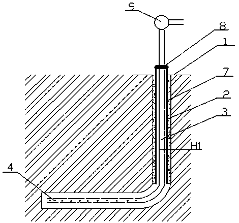
[0024] This implementation mode provides a kind of brine extraction device by screen tube method, such as figure 1 , is mainly composed of a deviated well 1, a deviated well casing 2, a center pipe 3 with a closed end and a water injection pump 9. The deviated well casing 2 is placed in the vertical section of the deviated well 1, and the outer wall of the deviated well casing 2 The inner wall of the well 1 is sealed with concrete 7; the central pipe 3 is placed in the casing 2 of the deviated well, and there is a preset distance H1 between the inner wall of the casing 2 of the deviated well and the outer wall of the central pipe 3, and the two are supported by The frame 8 is fixedly connected; the lower part of the central pipe 3 extends to overlap with the horizontal section of the inclined shaft 1, and a section of the side wall where the central pipe 3 overlaps with the horizontal section of the inclined shaft 1 has a number of water spouts 4 distributed along its length di...

Embodiment approach 2

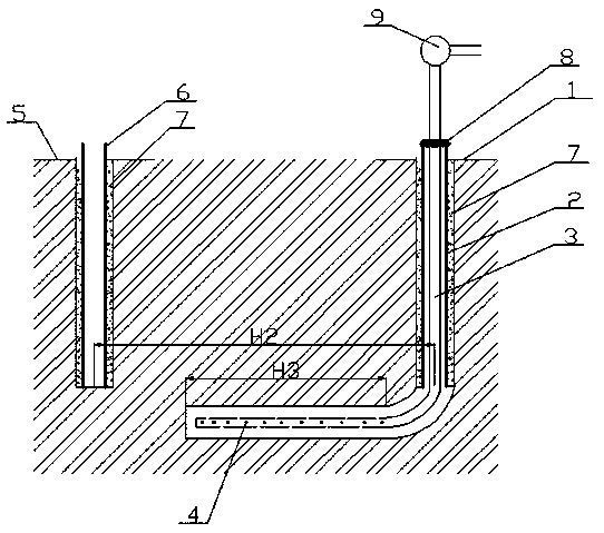
[0028] This embodiment is a further improvement of Embodiment 1. The main improvement is that in Embodiment 1, in practical applications, the length of the underground horizontal section of the inclined shaft 1 may be two to three hundred meters long. Under the action of water pressure, the water with high concentration needs to first pass through the horizontal section of the inclined well 1, then through the vertical section of the inclined well 1, and rise up through the space between the casing pipe 2 and the central pipe 3 of the inclined well to spray out the inclined wellhead. When the length of the underground horizontal section of 1 is long, the water pressure may not be able to press out the high-concentration water, or the press-out speed is relatively slow, but this embodiment can effectively solve the above problems.

[0029] Specifically, in this embodiment, as figure 2 As shown, another vertical well 5 is opened at a preset distance from the inclined well 1. Th...

Embodiment approach 3

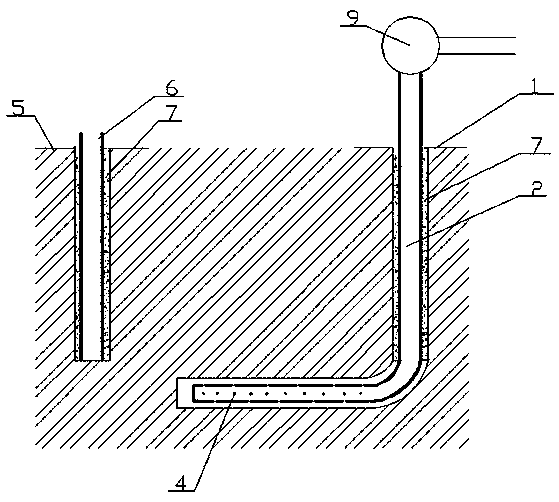
[0033] This implementation mode provides a kind of brine extraction device by screen tube method, such as image 3As shown, it is mainly composed of a vertical well 5, a vertical well casing 6, an inclined well 1, an inclined well casing 2 with a closed end, and a water injection pump 9. The vertical well 5 and the vertical section of the inclined well 1 are arranged in parallel, and the vertical well 5 and the inclined well 1 The distance H2 between them is greater than or equal to the length H3 of the horizontal section of the deviated well 1; the vertical well casing 6 is placed in the vertical well 5, and the outer wall of the vertical well casing 6 and the inner wall of the vertical well 5 are sealed by concrete 7 . The inclined well casing 2 is placed in the inclined well 1, and the outer wall of the vertical section of the inclined well casing 2 and the inner wall of the vertical section of the inclined well 1 are sealed by concrete 7 . The lower part of the inclined we...


PUM


Abstract

The invention relates to the technical field of mining and discloses a sieve tube process brine extraction device which comprises an inclined shaft (1), an inclined shaft casing pipe (2) and a centralpipe (3), wherein the tail end of the central pipe (3) is sealed; the inclined shaft casing pipe (2) is positioned in the vertical section of the inclined shaft (1); the central pipe (3) is positioned in the inclined shaft casing pipe (2); a preset distance H1 is formed between the inner wall of the inclined shaft casing pipe (2) and the outer wall of the central pipe (3); the lower part of the central pipe (3) extends to be overlapped with the horizontal section of the inclined shaft (1); and a plurality of water orifices (4) are formed in the side wall of the section, overlapped with the horizontal section of the inclined shaft (1), of the central pipe (3) in the length direction of the central pipe (3). Compared with the prior art, through adding the simple central pipe, the sieve tubeprocess brine extraction device can greatly increase the mining coefficient, is simple in structure, convenient to implement and saves energy and reduces emission.

Description

technical field [0001] The invention relates to the technical field of mining, in particular to a brine extraction device by screen tube method. Background technique [0002] At present, in the process of collecting Glauber’s salt ore, it is necessary to use vertical shafts and inclined shafts adjacent to each other. The two are connected at the location of Glauber’s salt mines about 2,000 meters underground, or there is a distance that can be dissolved after water injection. To collect the thenardite ore between the two, pump low-concentration water from the vertical shaft (or inclined well) into the ground through the water injection pump, dissolve the underground thenardite ore, and dissolve the high-concentration water mixed with thenardite ore Under the action of water pressure, it is ejected from the inclined shaft (or vertical shaft) to complete the collection of thenardite ore. [0003] The design of the above-mentioned vertical shafts and inclined shafts has the fo...

Claims


Application Information

Patent Timeline
Patent Type & Authority Applications(China)
IPC IPC(8): E21B43/29
CPCE21B43/29
Inventor 张国红李学楷
Owner 南风集团淮安元明粉有限公司
Why Eureka
Try Eureka