
Feed-back control system for heat exchanger with natural shedding frequency

a control system and heat exchanger technology, applied in the direction of instruments, heat measurement, force/torque/work measurement, etc., can solve the problems of noise, large amount of energy and excessive components, and heat transfer does not take place dynamically, and achieve the effect of maximizing heat transfer efficiency

Inactive Publication Date: 2007-11-13
BSTECH
View PDF10 Cites 1 Cited by
  • Summary
  • Abstract
  • Description
  • Claims
  • Application Information

AI Technical Summary

Benefits of technology

"The invention proposes a system for controlling a heat exchanger using flow resonance phenomenon. This system maximizes heat transfer efficiency by creating flow disturbances in the heat transfer medium caused by continuous pulses of excitation at the same frequency as the detected and calculated resonance frequency of the medium. The technical effects of this system include improved heat transfer efficiency and reduced energy consumption."

Problems solved by technology

Convection heat transfer does not take place dynamically for a laminar flow because of its poor fluid mixing effect.
So, for the promotion of convection heat transfer, a method of transition of fluid into a turbulence flow by means of acceleration of fluid is used, but the acceleration of fluid is accompanied by some disadvantages that a lot of energy and excessive components are needed and noise is produced.
But, for this simple vibrating method does not consider the physical properties of a fluid, increasing rate is insignificant in comparison with the energy necessary for the excitation.
So, it is very difficult to detect the flow characteristic factors which affect heat transfer to a large extent and to carry out the analysis of flow resonance frequency.
Accordingly, with the present know-how, there are some limitations in the application of the aforementioned technology.
Accordingly, A application of the corresponding technology is limited to a heat transfer medium of the gas and to cooling the components inside the case of a computer or a communication device, where natural convection takes place, and has a disadvantage of the difficulty in applying it to a heating medium of the liquid or to forced convection accompanied heat transfer medium.

Method used


Image

  • Feed-back control system for heat exchanger with natural shedding frequency
  • Feed-back control system for heat exchanger with natural shedding frequency
  • Feed-back control system for heat exchanger with natural shedding frequency

Examples


Embodiment Construction

[0021]Hereinafter, preferred embodiments of the invention will be described in detail with referenced to the appended drawings.

[0022]Prior to the description, it should be noted that terms and words used in the description and claims must not be limited and interpreted to be typical or literal, and should be construed as the meaning and concept conforming to the technical spirit of the invention on the basis that the inventor can define the concept of the terms and words to describe the invention in a best way.

[0023]Accordingly, since the embodiments described in the present invention and configurations shown the drawings are the most preferred embodiments only and do not represent all of technical spirit of the invention, it should be understood that there may be various equivalents and modification examples that may replace them at the time of application of the present invention.

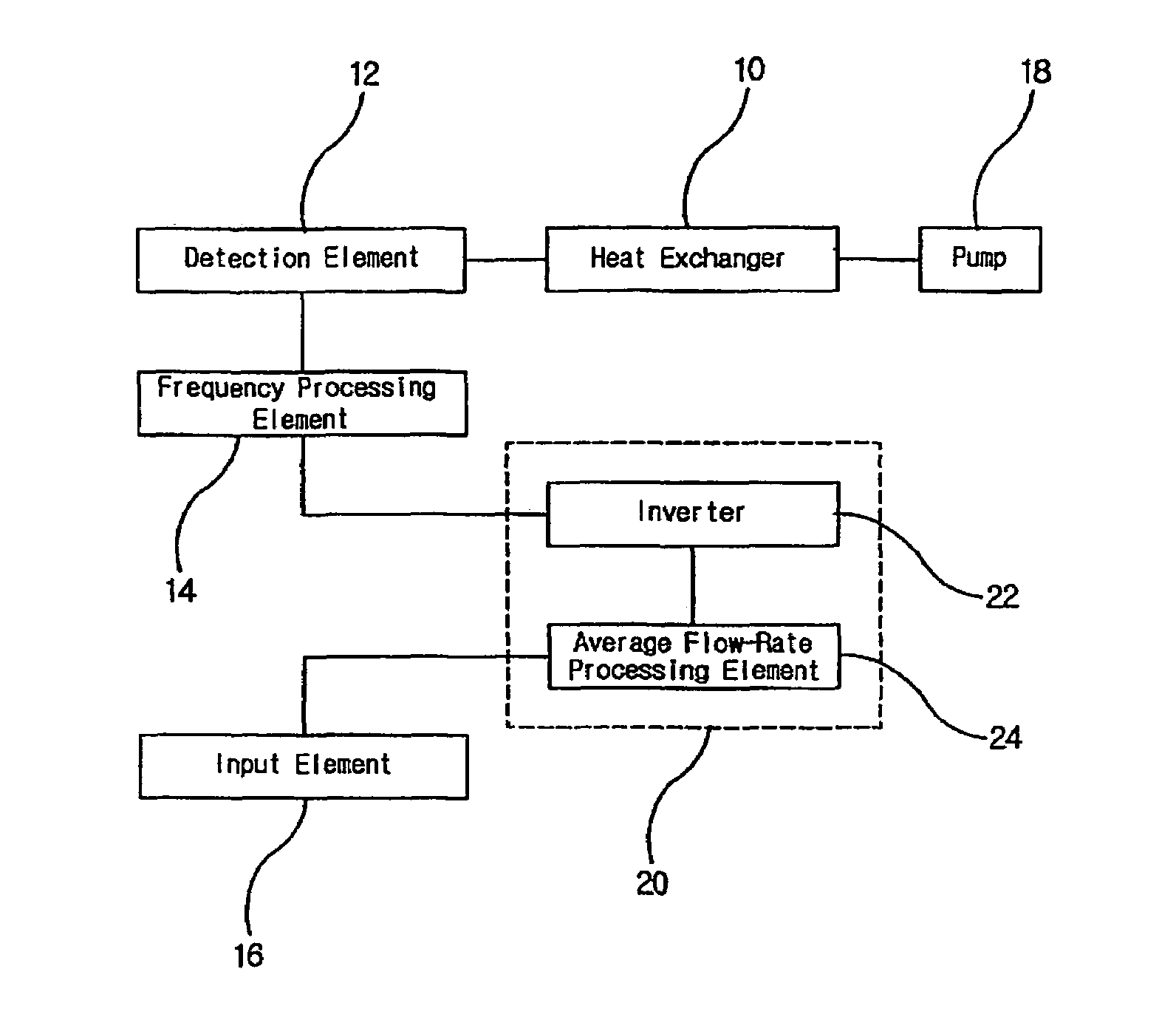
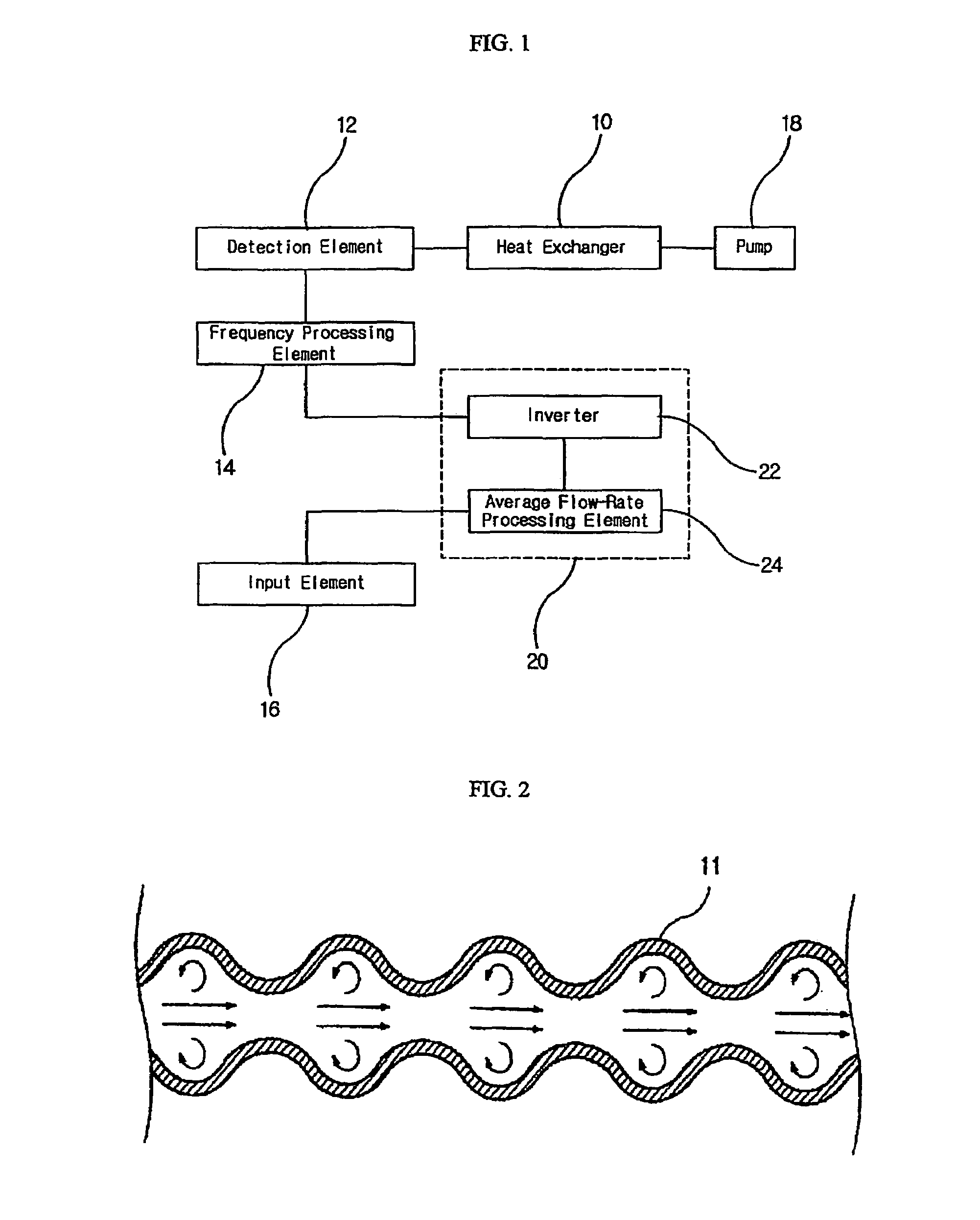
[0024]FIG. 1 shows schematically a block configuration of flow resonance feed-back control system for ...


PUM

PropertyMeasurementUnit
resonance frequencyaaaaaaaaaa
frequencyaaaaaaaaaa
processingaaaaaaaaaa

Abstract

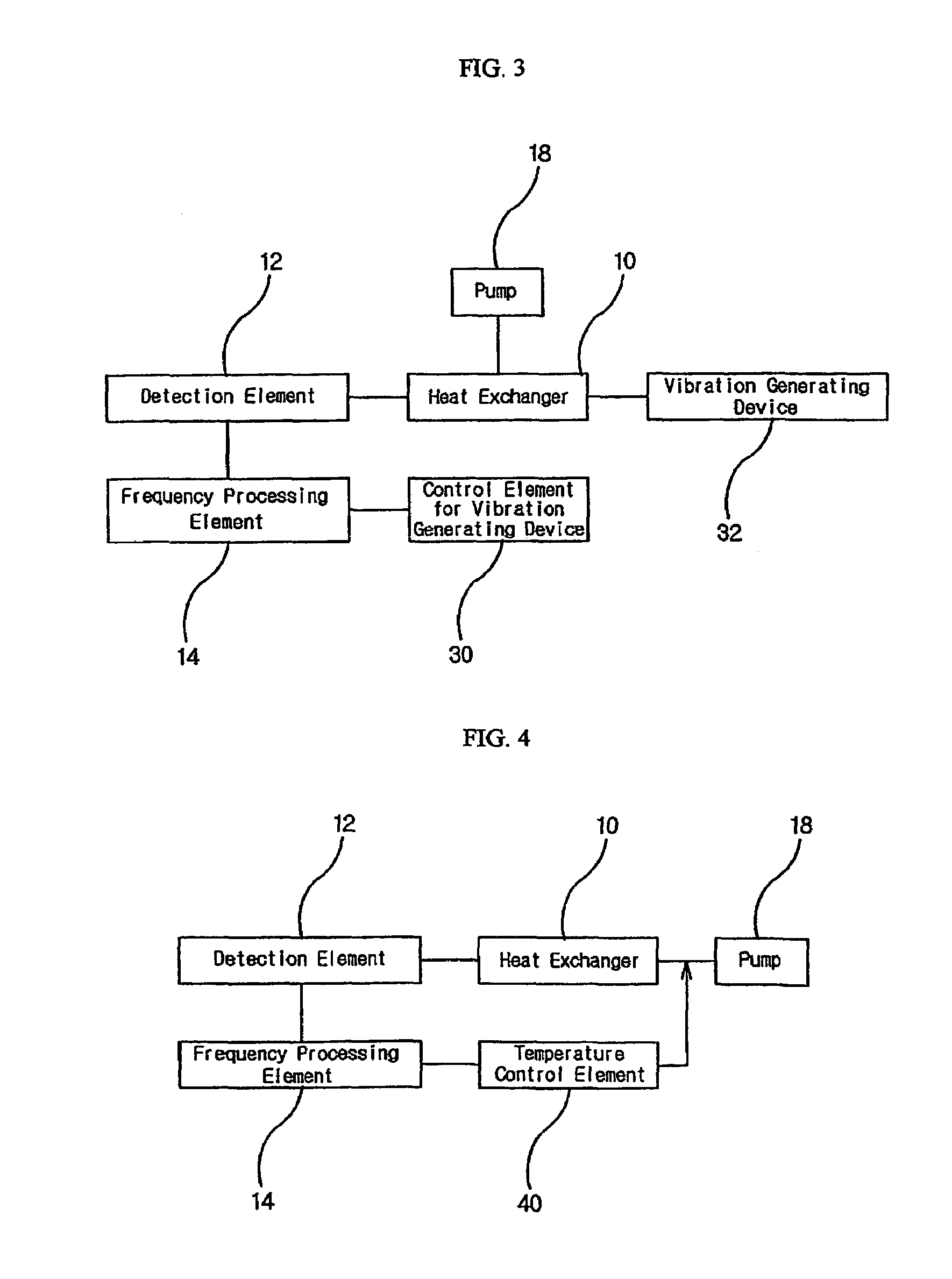
The invention relates with the feed-back control system of a heat exchanger by use of the flow resonance phenomenon which maximizes the heat transfer efficiency by generating the flow disturbances of a heat transfer medium. If a heat transfer medium is periodically stimulated at the characteristic frequency of a heat exchanger, the flow resonance frequency, which is dependent upon the flow conditions of heat transfer medium and the geometries of a heat exchanger, the disturbances of heat transfer medium is increased to the extent that heat transfer is dramatically high. This system is composed of the detecting part for the detection of flow characteristics, the processing part for the determination of flow resonance frequency, and the stimulating part which excites a heat transfer medium at the calculated flow resonance frequency.

Description

TECHNICAL FIELD[0001]The present invention relates to the control system for a heat exchanger, and more particularly to the flow resonance feed-back control system for a heat exchanger, which maximizes heat transfer efficiency by means of flow disturbances resulted from the continuous pulses excitation of a heat transfer medium with the same period as the detected and calculated resonance frequency of a heat transfer medium, of which function is the heat transfer in a heat exchanger.BACKGROUND OF THE ART[0002]A heat exchanger is used in such various fields as a heater, a cooler, a evaporator, a condenser, etc. and plays a role of supplying a target fluid with some heat and taking some heat from that fluid. The former function is carried out by a heating medium and the later by a cooling medium respectively, and the heating medium and the cooling medium is said to be a heat transfer medium in a common name.[0003]The most used one among many types of heat exchangers is the metal tube ...

Claims


Application Information

Patent Timeline
Patent Type & Authority Patents(United States)
IPC IPC(8): G01K17/06G01L1/10F28F27/00F28F13/10
CPCF28F27/00F28F13/10F28F3/046F28D9/00
Inventor LEE, SEUNGYOUP
Owner BSTECH
Learn More