
Acoustic attenuation device and methods of producing thereof

Inactive Publication Date: 2017-07-13
CHEN SHU CHUN
View PDF6 Cites 3 Cited by
  • Summary
  • Abstract
  • Description
  • Claims
  • Application Information

AI Technical Summary

Benefits of technology

This patent discloses a tiny device that helps reduce harmful sounds while allowing for low-level ambient sounds to be detected. The device is designed to improve the ability to hear important communication without risking damage to the hearing. The device uses a micro-fabrication process to create a thin and lightweight device. It is effective at reducing impact noise while maintaining good acoustic performance on normal sounds. The device has a minimum attenuation of 30 dB for sounds below a certain threshold level, and operates at different sound levels. The device is designed to protect against noise-related tinnitus and hearing loss.

Problems solved by technology

Even in developed countries hearing impairment continues to remain a common health disorder, leaving a largely untapped market to be exploited.
Most important of all, the membrane is not flexible enough to function at a low sound threshold value.
Second, during the normal sound regime, the existing membrane attenuates greatly due to the thick membrane and distorts the signal tremendously due to the uneven membrane stress.
Such attenuation distorts the signal making users difficult to hear and understand speech properly.
Third, in the maximum sound regime, the existing membrane still deflects due to high membrane elasticity and thus attenuates ineffectively.
Finally, since there is no quality control on membrane manufacturing (such as internal stress, and thickness), attenuation varies from device to device.

Method used


Image

  • Acoustic attenuation device and methods of producing thereof
  • Acoustic attenuation device and methods of producing thereof
  • Acoustic attenuation device and methods of producing thereof

Examples


Embodiment Construction

[0027]Various embodiments are described in detail with reference to a few examples thereof as illustrated in the accompanying drawing. In the following description, numerous specific details are set forth in order to provide a thorough understanding of this disclosure. It will be apparent, however, to one skilled in the art, that additional embodiments may be practiced without some or all of these specific details. Additionally, some details may be replaced with other well-known equivalents. In other instances, well-known process steps have not been described in detail in order to not unnecessarily obscure the present disclosure.

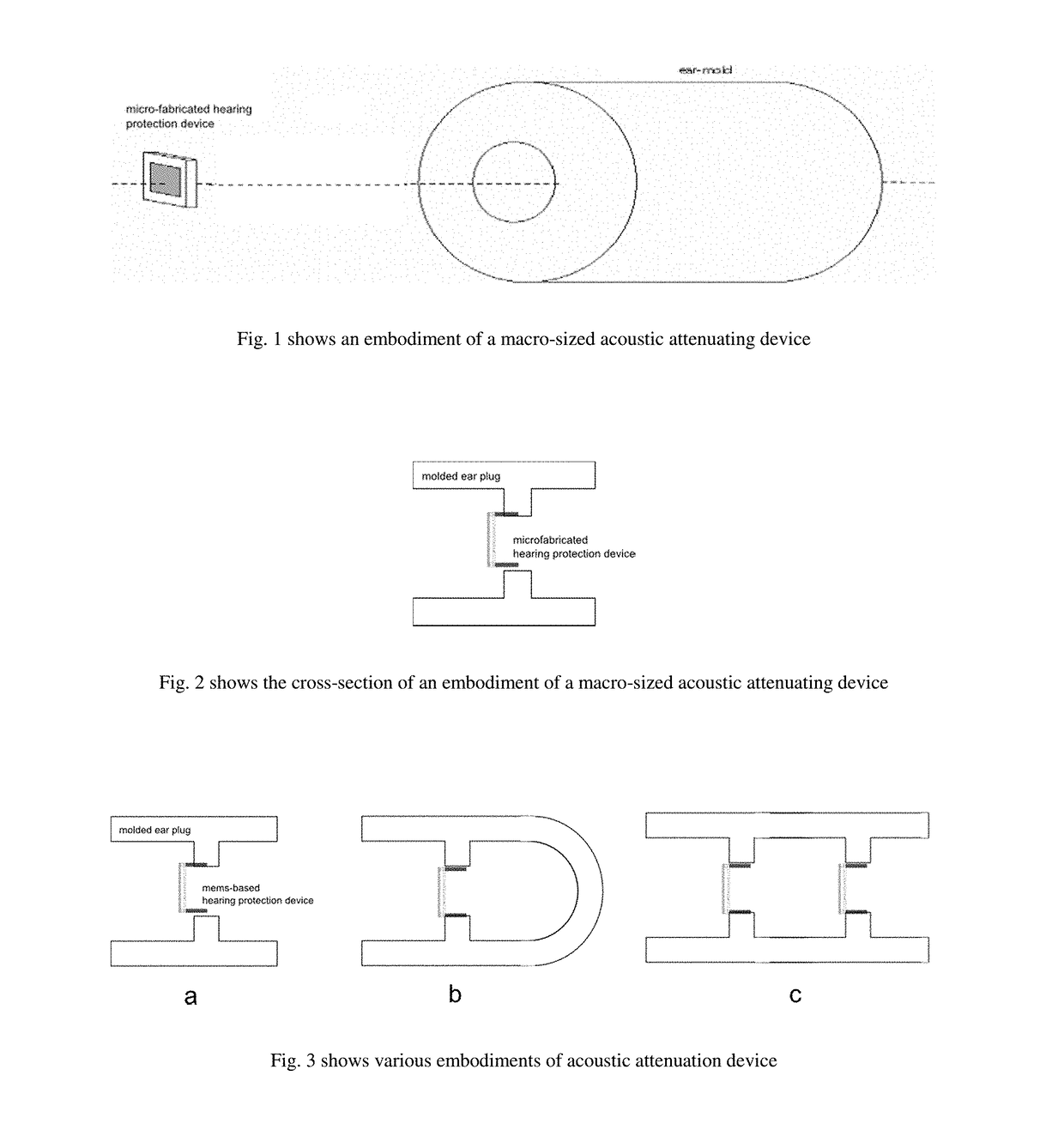
[0028]FIG. 1 shows the schematics of a macro-sized acoustic attenuation device featuring an ear-mold embedding a hollow passageway for passing external sound through a micro-fabricated acoustic attenuation device whereby the silicon chip is attached to the ear-mold. The assembly of such embodiment could be rather simple. The lightweight device is a passive n...


PUM


Abstract

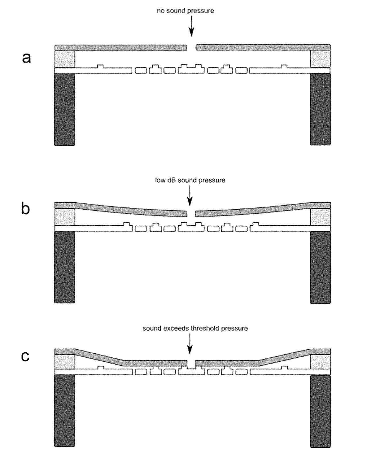
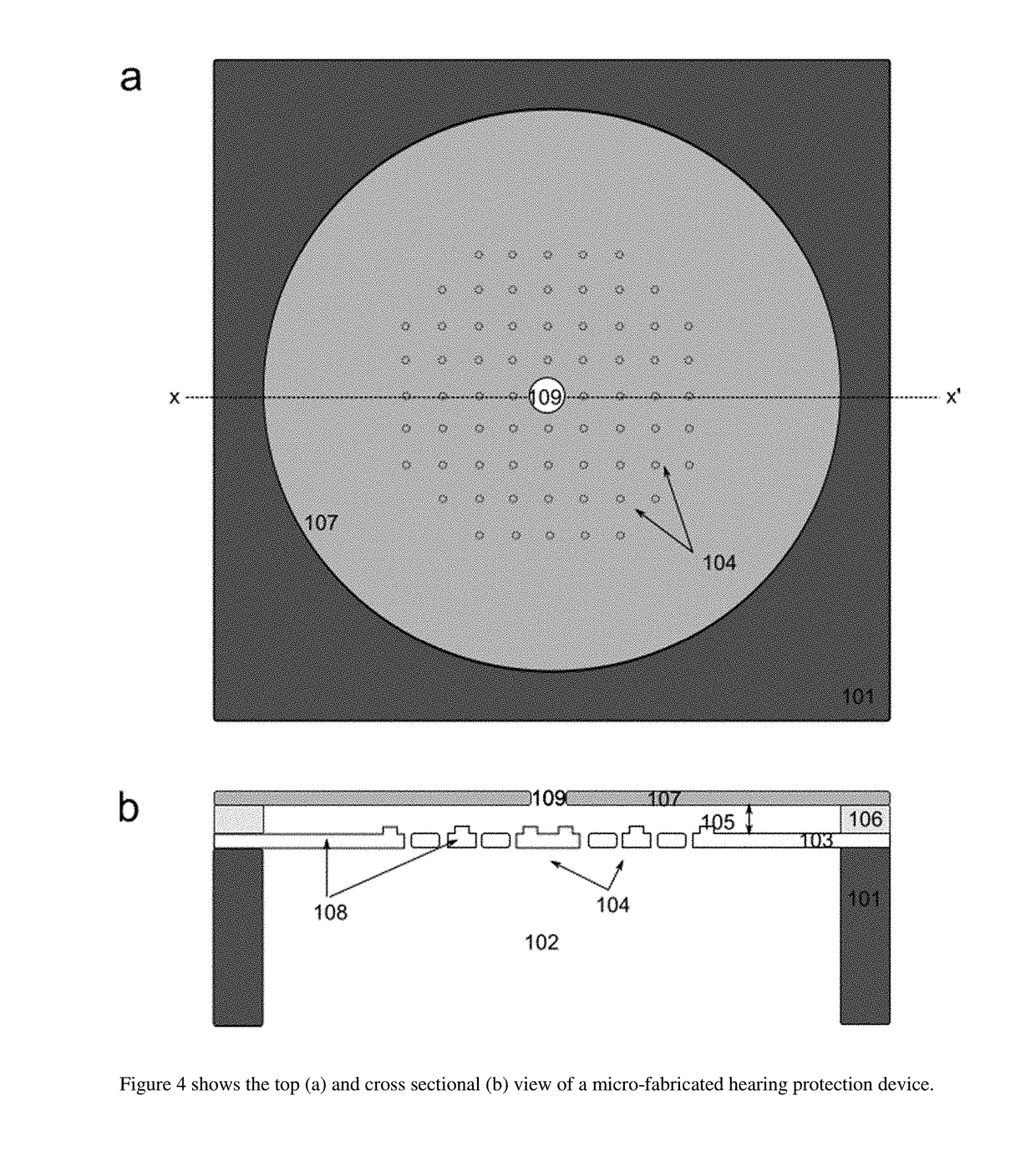
Micro-fabricated acoustic attenuation devices are described. One such device includes 1) a substrate, 2) a movable diaphragm supported by springs that anchors to the substrate, and 3) a stationary proliferated backplane which is separated by an air gap, whereby sound pressure causes the movable diaphragm to vibrate and when the sound exceeds threshold, the movable diaphragm deflects and presses against the proliferated backplane restricting further movement thus attenuates incoming sound.Another device includes 1) a substrate, 2) a movable diaphragm wherein the diaphragm has at least one hole on it, and 3) a stationary proliferated backplane which is separated by an air gap, whereby sound pressure causes the movable diaphragm to vibrate and when the sound exceeds threshold, the movable diaphragm deflects and presses against the proliferated backplane restricting further movement thus attenuates incoming sound. Methods of producing the micro-fabricated acoustic attenuation device are also described.

Description

CROSS-REFERENCE TO RELATED APPLICATIONS[0001]This application claims priority to Provisional Application No: 62 / 276,805, filed on Jan. 8, 2016STATEMENT REGARDING FEDERALLY SPONSORED RESEARCH OR DEVELOPMENT[0002]N / ABACKGROUND[0003]Field of the Technology[0004]The present invention relates to a passive micro-fabricated acoustic attenuation device and in particular may be used in conjunction with macro-sized acoustic devices such as ear plugs, ear phones, headphones, helmets, and microphone housings.[0005]Background[0006]Noise Induced Hearing Loss (NIHL) is one of the major avoidable occupational hazards, particularly in developing countries, where occupational and environmental noise remains the major risk factor for hearing impairment. Even in developed countries hearing impairment continues to remain a common health disorder, leaving a largely untapped market to be exploited. More than 120 million workers across the globe are exposed to dangerously high noise levels (over 85 dB). Th...

Claims


Application Information

Patent Timeline
IPC IPC(8): G10K11/162A61F11/08A61F11/14G10K13/00
CPCG10K11/162G10K13/00A61F2011/085A61F11/14A61F11/08H04R7/26H04R2207/021G10K11/16G10K11/04A61F11/085A61F11/145
Inventor CHEN, SHU CHUN
Owner CHEN SHU CHUN
Learn More