
Directed image capture

a technology of image capture and image data, applied in the field of directed image capture systems, can solve the problems of difficult update, difficult to provide robust real-time image data analytics for various consumer and commercial use cases, and limited texture resolution of 3d maps,

Active Publication Date: 2017-07-20
HOVER
View PDF3 Cites 17 Cited by
  • Summary
  • Abstract
  • Description
  • Claims
  • Application Information

AI Technical Summary

Benefits of technology

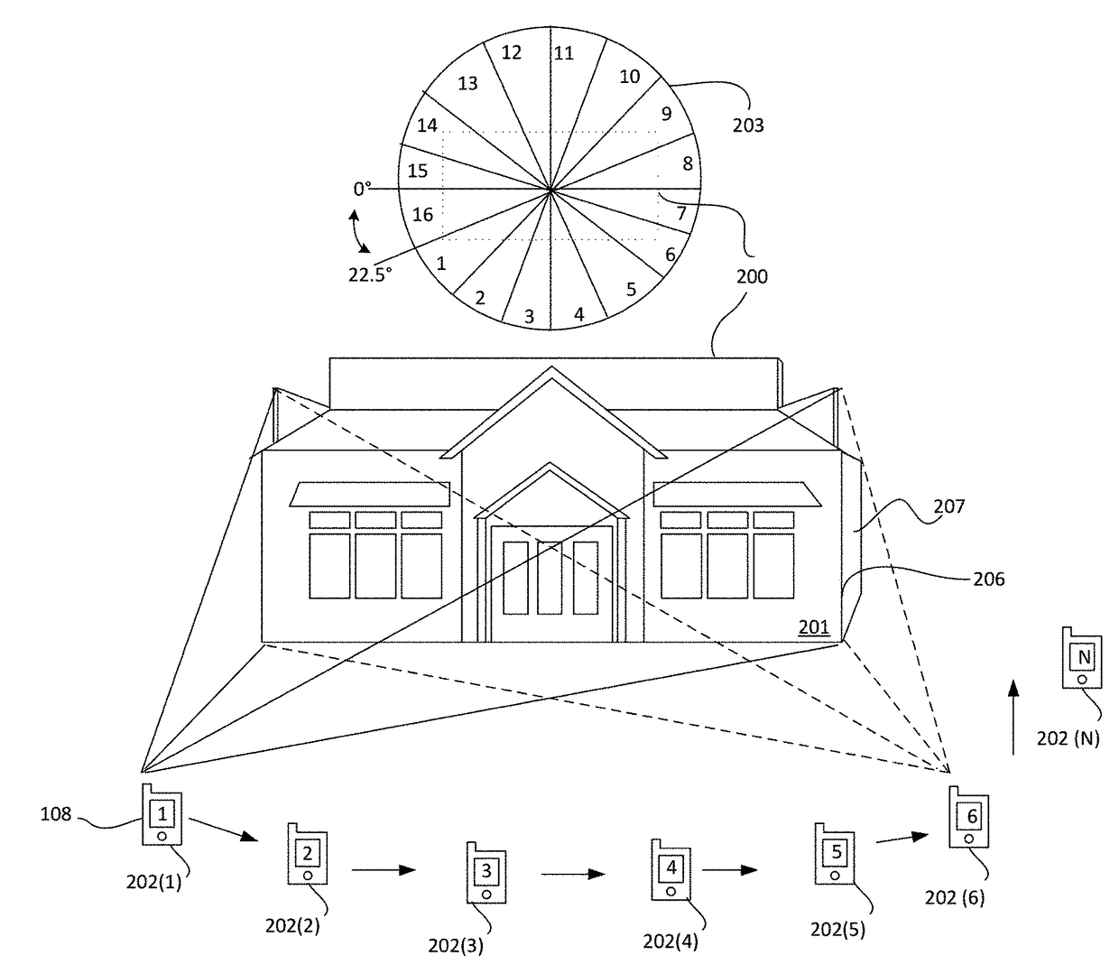
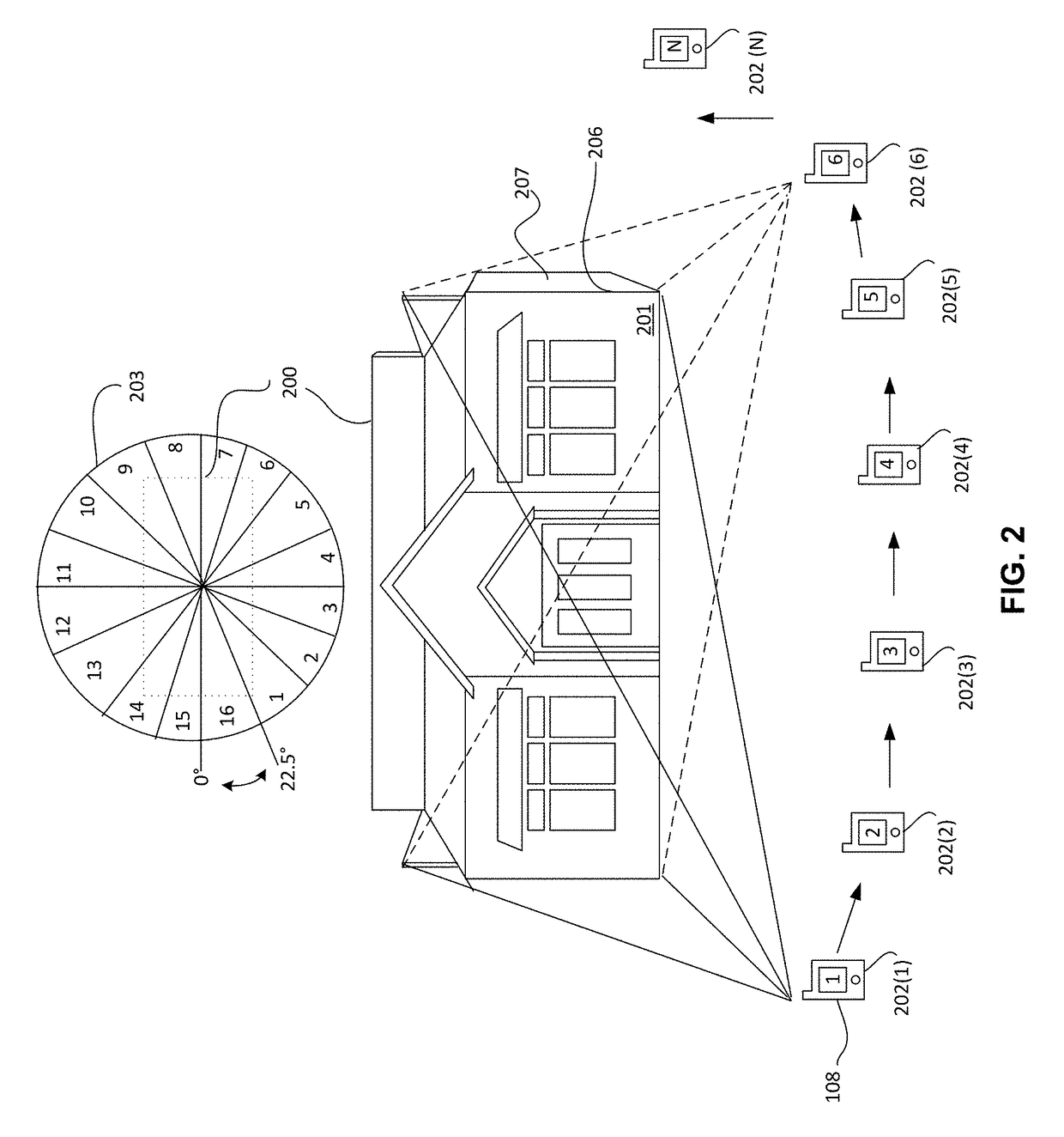
The present patent application claims priority to several related patent applications, including U.S. Utility patent application Ser. No. 15 / 348,038, which claims priority to U.S. Utility patent application Ser. No. 15 / 156,587, which is a continuation-in-part of U.S. Utility patent application Ser. No. 15 / 348,038, which claims priority to U.S. Provisional Application No. 62 / 253,441, which is an image frame classifier. The patent describes a system architecture and process for creating a directed image capture system that can capture high-quality images of buildings and create multi-dimensional models of them. The system uses guide overlays to accurately capture images of buildings and provide real-time image data analytics for various consumer and commercial use cases. The patent also describes a digital view finder with a centered ground-level image of a building and a process for monitoring the quality of the image capture. The patent aims to improve the accuracy and texture resolution of 3D models of buildings and provide better texture and geometry quality, affordable cost, and robust real-time image data analytics for various consumer and commercial use cases.

Problems solved by technology

However, these 3D maps have limited texture resolution, geometry quality, accurate geo-referencing and are expensive, time consuming and difficult to update and provide no robust real-time image data analytics for various consumer and commercial use cases.

Method used


Image

  • Directed image capture
  • Directed image capture
  • Directed image capture

Examples


Embodiment Construction

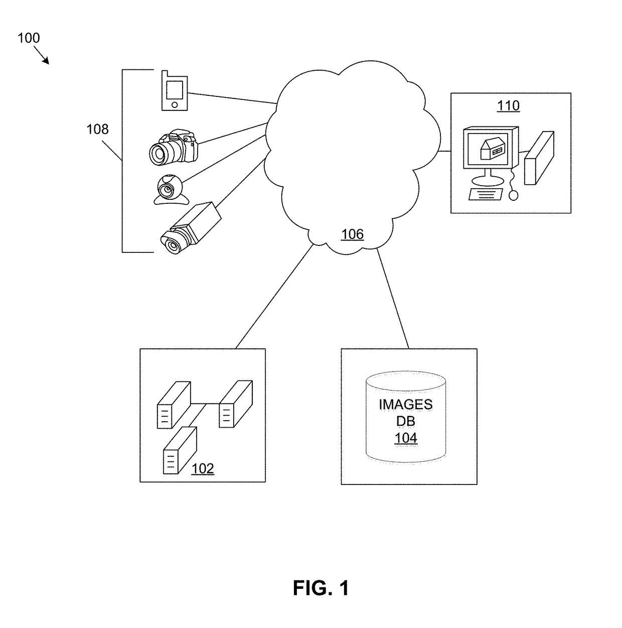
[0018]FIG. 1 illustrates one embodiment of system architecture in accordance with the present disclosure. In one embodiment, image processing system 100 includes image processing servers 102. Image database (DB) 104 and image processing servers 102 are coupled via a network channel 106.

[0019]Network channel 106 is a system for communication. Network channel 106 includes, for example, an Ethernet or other wire-based network or a wireless NIC (WNIC) or wireless adapter for communicating with a wireless network, such as a WI-FI network. In other embodiments, network channel 106 includes any suitable network for any suitable communication interface. As an example, and not by way of limitation, the network channel 106 can include an ad hoc network, a personal area network (PAN), a local area network (LAN), a wide area network (WAN), a metropolitan area network (MAN), or one or more portions of the Internet or a combination of two or more of these. One or more portions of one or more of t...


PUM


Abstract

A process is provided for guiding a capture device (e.g., smartphone, tablet, drone, etc.) to capture a series of images of a building. Images are captured as the camera device moves around the building—taking a plurality of images (e.g., video) from multiple angles and distances. Quality of the image may be determined to prevent low quality images from being captured or to provide instructions on how to improve the quality of the image capture. The series of captured images are uploaded to an image processing system to generate a 3D building model that is returned to the user. The returned 3D building model may incorporate scaled measurements of building architectural elements and may include a dataset of measurements for one or more architectural elements such as siding (e.g., aluminum, vinyl, wood, brick and / or paint), windows, doors or roofing.

Description

CROSS REFERENCE TO RELATED PATENTS[0001]The present U.S. Utility Patent Application claims priority pursuant to 35 U.S.C. §120 as a continuation-in-part of U.S. Utility application Ser. No. 15 / 348,038, entitled “DIRECTED IMAGE CAPTURE,” filed Nov. 10, 2016, which is a continuation-in-part of U.S. Utility application Ser. No. 15 / 166,587, entitled “GRAPHICAL OVERLAY GUIDE FOR INTERFACE,” filed May 27, 2016, which claims priority pursuant to 35 U.S.C. §119(e) to U.S. Provisional Application No. 62 / 168,460, entitled “GRAPHICAL OVERLAY GUIDE FOR INTERFACE,” filed May 29, 2015, all of which are hereby incorporated herein by reference in their entirety and made part of the present U.S. Utility Patent Application for all purposes.[0002]U.S. Utility application Ser. No. 15 / 348,038 claims priority pursuant to 35 U.S.C. §119(e) to U.S. Provisional Application No. 62 / 253,441, entitled “IMAGE FRAME CLASSIFIER,” filed Nov. 10, 2015, which is hereby incorporated herein by reference in its entirety...

Claims


Application Information

Patent Timeline
Patent Type & Authority Applications(United States)
IPC IPC(8): H04N5/232H04N13/02G06T7/00H04N13/221
CPCH04N5/23222G06T7/0002G06T2207/10004H04N13/0221G06T2207/10016H04N5/23293H04N1/2104H04N2013/0081H04N13/221H04N13/296H04N1/00167H04N1/00183H04N1/00244H04N1/2166H04N2201/0084H04N23/661H04N23/64H04N23/634
Inventor CASTILLO, WILLIAMHALLIDAY, DEREKUPENDRAN, MANISH
Owner HOVER
Learn More